Quantcast
Channel: destevez – Daniel Estévez
Viewing all 500 articles
Browse latest View live

Concurso Atlántico V-UHF

$
0
0

Today, I've participated in this month's national V-UHF from Cerro de San Pedro, SOTA summit EA4/MD-020 (1425m). I arrived the summit a bit before 10:00UTC and worked until the end of the contest (14:00UTC). The equipment was the usual: a Yaesu FT-817ND and an Arrow satellite yagi antenna (3 elements in 144MHz and 7 elements in 432MHz).

Find below the map of stations worked. My location is in red, stations worked both in 144MHz and 432MHz are in green and stations worked only in 144MHz are in blue.

Propagation didn't seem so good as in last month's contest. In fact, if you cross check the maps of both contests, you can see the difference. A few stations complained that they were having trouble getting out in 23cm. Also, activity was lower. It seems that there is more activity earlier in the morning (around 7:00UTC and 8:00UTC), when people wake up and get a bit of radio time before having to attend their daily chores. At 13:00UTC, almost everybody had gone QRT. This is not surprising, as this time coincides with the Spanish usual lunch time.

After the contest finished, I called for about 20 or 30 minutes in 145.500MHz FM to let people have a chance to work the SOTA summit. I managed to contact 5 stations: EA4GLI, EA4BVL, EA4GMO and my friends Luis EC4TR and EA4SG with whom I had a small chat before hiking down from the summit. EA4BVL made a small test transmitting with only 200mW. He was S9+ on my FT-817ND when my yagi was pointing more or less in his direction. I tried to point my yagi off to one side to see how low his signal would get. I managed to get him in one of the nulls and lose his signal completely. However, moving the yagi 10º from this position made his signal go back to about S6. This is not so surprising, since I probably had him almost in line of sight. Still a good show of how far can 200mW get you. What is a bit surprising is that EA4GLI reported that he was also hearing EA4BVL at S9+.


Phase noise of 27MHz references for a Ku-band LNBF

$
0
0

Today, I've being measuring the phase noise of the different 27MHz references that I have for my Ku-band LNBF. The LNBF is an Avenger PLL321S-2. I've modified it, removing the 27MHz crystal and including a connector for an external 27MHz reference signal. In my lab, I have the following equipment to generate a 27MHz signal:

  • OCXO/Si5351A kit. This kit includes a 27MHz OCXO and a Si5351A frequency synthesizer. The Si5351A can act as a buffer and output the OCXO signal directly or generate a 27MHz clock.
  • A DF9NP 27MHz PLL and a DF9NP GPSDO. The GPSDO generates a 10MHz signal which is locked to GPS. The PLL generates a 27MHz from the 10MHz signal.

I've used linrad to receive the beacon of BADR-5 at 11966.2MHz using different references for the 27MHz signal. The AFC in linrad tries to compensate for any drift in the reference or the satellite beacon. By averaging, one can get good plots of the sideband noise of the beacon. This is far from a proper lab test, but it gives a good idea of the performance of the references.

The first reference tested is the 27MHz OCXO, using the Si5351A as an output buffer. As we can see, the phase noise is quite low. This can be expected for a crystal oscillator.

27MHz OCXO (Si5351A XO buffer output)

The next reference tested is the Si5351A generating a 27MHz signal. The phase noise is almost the same as before.

Si5351A with 27MHz OCXO

Next, we test the 27MHz PLL in "free-run" mode. Since the PLL contains a 27MHz VCXO, it will oscillate at about 27MHz even if no 10MHz input is supplied. The problem is that the 27MHz drifts a lot. As we can see, the AFC in linrad has trouble to compensate for all this drift, but nevertheless, it seems that the phase noise is also quite good.

Free running 27MHz PLL

Next, we generate a 10MHz signal with the Si5351A and feed it into the 27MHz PLL. The result is horrible. Perhaps the problem is that the 10MHz is unfiltered. It is not a sine wave, so it could give problems with the PLL.

Si5351A with 27MHz OCXO generating 10MHz and 27MHz PLL

Finally, we test the 27MHz PLL with the 10MHz GPSDO. We see that the phase noise is much higher than before, specially at 100Hz separation or less.

10MHz GPSDO and 27MHz PLL

The phase noise of the GPSDO + 27MHz PLL is actually very high. Of course, the LNBF multiplies the 27MHz signal to obtain a 10.6GHz LO, and this increases the phase noise by about 50dB. Thus, it is very important to have a very clean reference, paying special attention to very close separations. Still, the phase noise I get seems too much. I don't know if this is how these units are supposed to perform or if there is some sort of problem. I'll have to look into this more carefully.

Several 10GHz beacons on WebSDRs

$
0
0

I have being receiving several 10GHz on different WebSDRs with linrad to get a rough idea of the performance of the beacons and receivers, both in terms of frequency stability and phase noise. Here are the results.

First we look at the Paella Team SDR, located in IM98TJ, near Alicante. Luis EA5DOM reports that it is using a 27MHz PLL by DF9NP and a 10MHz OCXO. The antenna is an offset dish beaming to Ibiza to check for tropospheric propagation. The beacons ED5YAE and ED5YAF are received indirectly through reflections. They use PLLs to generate 10GHz, so their signals are not supposed to be very clean. There is also a Baofeng UV-3R used as a signal source.

ED5YAE is frequency locked to a GPSDO. We see that the frequency wobbles more or less 50Hz. Keep in mind that this is due to the combined effects of the GPSDO at ED5YAE and the OCXO at the WebSDR. The signal is spread about 30Hz. I don't know if this is due to the transmitter, the receiver, or propagation. We can also note a second "hump" of phase noise, about 200Hz wide. It is green on the waterfall.

Paella Team SDR. ED5YAE, CW

ED5YAF is near the receiver, so the signal is much stronger. Otherwise, phase noise and frequency stability are similar to ED5YAE. Since the signal is strong, phase noise is quite noticeable.

Paella Team SDR. ED5YAF, CW

The Baofeng also displays similar characteristics. This is curious. People report that the Baofeng is surprisingly quite stable in frequency. I haven't seen any measurements of its phase noise. I'll have to make some measurements on my own Baofeng.

Paella Team SDR. Baofeng UV-3R.

Luis EA5DOM also reports that frequently the beacons can be received through reflections on ships. This causes a Doppler shift of 200 to 300Hz. I haven't seen this reflections, but it would be very interesting to study them.

Next, we look at the SUWS WebSDR. The beacon GB3SEE can be received very strong in this SDR. GB3SEE is frequency locked, but the receiver is not (I think it uses an unmodified LNBF). Thus, frequency stability is not very good, but surprising for the unmodified LNBF. Phase noise is very good. Just look at the periods when the beacon transmits an unmodulated carrier.

SUWS SDR. GB3SEE, JT4G, FSK-CW and CW.

Now we look at a WebSDR in Dresden, locator JO61VA51. This SDR receives the beacon DM0TUD/B, but the frequency stability is very poor. Phase noise is very good.

Dresden SDR. DM0TUD/B, FSK-CW and CW

Finally, we look at a WebSDR in Belgium. The receiver is GPS locked. An unidentified beacon can be received there. The frequency stability is extremely good. The phase noise is also good, but if one looks carefully at the periods of unmodulated carrier, one can see a faint "green hump" about 10Hz wide. This will hardly cause any problem.

ON websdr. JT4G, FSK-CW and CW.

Ship reflection on ED5YAE 10GHz beacon

$
0
0

In my previous post, I mentioned the possibility of receiving 10GHz beacons reflecting off ships in the Mediterranean sea through the Paella Team WebSDR, in Alicante. Luis EA5DOM tells me that these reflections happen often. However, I didn't get any in the time I was doing the recordings for the previous post.

After making much longer recordings, I have seen a couple of reflections. I would say that a dozen or so happen every day. However, they last for quite long. Here you can see a reflection lasting for almost 20 minutes. The Doppler shift ranges between -300Hz and -200Hz. At its strongest moment, the reflection is only 10dB weaker than the beacon.

ED5YAE: direct signal and reflection

Phase noise of a Baofeng UV-5R 10GHz signal

$
0
0

Several of the Baofeng chinese handheld radios generate a weak 10GHz signal while in receive mode. Thus, they are a popular cheap and quick 10GHz signal source for tests. To generate a 10GHz signal, you have to tune the Baofeng to the 70cm band (for instance, 432MHz). The radio will generate a weak 24th harmonic while in receive mode. If you want a steady carrier, you have to set the squelch to zero. Otherwise you will just get beeps as the radio wakes up periodically to check for a signal. Lately, I've being investigating phase noise and reciprocal mixing of 10GHz receiver systems. A natural question is how good is the phase noise of a Baofeng used as a 10GHz signal source and whether it can be used to check if the phase noise performance of a receiver is acceptable. It turns out that it is not so noisy as one may first think.

Below you can see the Baofeng signal received with my PLL based LNBF with external reference. Here, the external reference I'm using the DF9NP 27MHz PLL in free-run mode (no 10MHz input). As the PLL has now being running for days, it is quite stable in free-run mode, so linrad's AFC has no problem tracking the signal (compare with the recording of the beacon of BADR-5, where the PLL had being running just for a few hours and was very unstable).

In my opinion, a system having this amount of close-in phase noise would not be perfect, but acceptable.

Baofeng UV-5R 10GHz harmonic. Received with free-running DF9NP 27MHz PLL

Now compare the same signal received using the DF9NP GPSDO and 27MHz PLL. We see the usual "hump" of phase noise that we've seen in previous posts.

Baofeng UV-5R 10GHz harmonic. Received with DF9NP GPSDO and 27MHz PLL

Thus, I would say that the signal of a Baofeng UV-5R is acceptable for checking the phase noise performance of a receiver. A system which is cleaner than the Baofeng is good. A system which is dirtier may be inadequate for some purposes.

Compare also the fist figure above with the recording of a Baofeng UV-3R in the Paella Team WebSDR. The second is much dirtier. One can imagine that the 10GHz signals of a Baofeng UV-3R and UV-5R are quite similar. Therefore, it seams that the Paella Team WebSDR has some problems regarding phase noise. Luis EA5DOM reports that it is using a DF9NP 27MHz PLL and a 10MHz OCXO.

Update on phase noise of 27MHz references

$
0
0

This is a follow up to a previous post where I investigated the phase noise of 27MHz references to be used for a 10GHz receiver. Dieter DF9NP has being kind enough to send me a 10MHz 0.25ppm TCXO to do some more tests.

I've connected the 10MHz TCXO to the DF9NP 27MHz PLL and used it to receive the beacon of BADR-5, as I did in the previous post. The phase noise of the 10MHz TCXO + 27MHz PLL can be seen in the following figure.

10MHz 0.25ppm TCXO and 27MHz PLL

For comparison, see below the phase noise with the DF9NP 10MHz GPSDO and 27MHz PLL. There is not much difference between both. This seems to indicate that the culprit of the phase noise is the 27MHz PLL, as the 10MHz TCXO should be quite clean.

10MHz GPSDO and 27MHz PLL

Arduino aquarium controller

$
0
0

Just a quick note that I've finally put the page for my Arduino aquarium controller. This is a project that I built several years ago to control a small aquarium at home. I built it with through-hole parts on a home etched single-side PCB. Now I've redesigned the project to use SMD parts and double-sided PCB.

Aquarium controller board (front)

Improving phase noise performance of the DF9NP 27MHz PLL

$
0
0

In some of the latest posts, I've being talking about the phase noise performance of 10GHz receivers, and in particular, of 27MHz references for Ku-band LNBFs (1, 2, 3, 4). Indeed, this started when I checked the performance of my new 10MHz GPSDO and 27MHz PLL by DF9NP and I wasn't too happy with the phase noise.

After working with Dieter DF9NP in investigating this problem and performing several tests, Dieter found that the problem was likely in the loop bandwidth of the 27MHz PLL. The loop filter bandwidth is 50Hz. He proposed the following component modifications to change the bandwidth to 300Hz.

Modification of the PLL loop (new values in red)
Modification of the PLL loop filter (new values in red)

After I performed the modifications, I was quite surprised and happy with the results. As always, I've used the beacon of BADR-5 at 11966.2MHz to test the phase noise performance. Linrad's AFC is in use. The result is below. As you can see, it is as good as the best references that I had tested before.

10MHz GPSDO and modified 27MHz PLL

For comparison, this was the performance before the modification. The difference is huge. Many thanks to Dieter for his effort and to Luis EA5DOM, who also participated in the discussion and gave some good advice.

10MHz GPSDO and 27MHz PLL

Concurso Nacional V-UHF

$
0
0

Today I've hiked up with my father to Siete Picos, SOTA summit EA1/SG-005 (2138m), to participate in this month's national V-UHF contest. We arrived and set up around 07:30UTC and worked until 11:30UTC, where activity became low, as most possible contacts were already done and people started to leave in order to prepare lunch. The equipment was a Yaesu FT-817ND and an Arrow yagi antenna (3 elements in 144MHz and 7 elements in 432MHz).

Below is the map of stations worked. My position is in red, stations worked both in 144MHz and 432MHz are in green and stations worked only in 144MHz are in blue. The black station is the odd one that I could only work in 432MHz. This can happen if you catch them first in 432MHz, then a big mess with several stations arises and you're unable to tell them to change to 144MHz to make the contact and decide that you'll catch them in 144MHz later, but you don't manage to find them later.

Propagation seemed very good today. Stations as far as 100 or 200km where as strong as if they were local, both in 144MHz and in 432MHz. Most stations were worked without too much effort (QRM permitting, of course). My results have being much better than in last year's August contest, where I worked from La Maliciosa, SOTA summit EA4/MD-007 at 2227m and got the 5th position and EA4 district record in the 6 hours category. Also, I think that this contest has being my best this season.

Checking my log (I use Tucnak on my smartphone)

Receiving the Vaisala RS92-SGP radiosonde launched from Madrid-Barajas

$
0
0

Each day, at 01:00UTC and 11:00UTC a Vaisala RS92-SGP radiosonde is launched from Madrid-Barajas airport. This is a small electronics package tied to a helium balloon that ascends up to between 24 and 28km high before bursting and descending on parachute. It is designed to measure atmospheric parameters on its way up. It includes temperature, pressure and humidity sensors, as well as a GPS receiver. The launch on Wednesdays at 11:00UTC also includes a plug-in ozone sensor (which is a much larger and more expensive package). The data is transmitted at 403MHz using Manchester-encoded 4800bps GMSK and protected using Reed-Solomon. You can find more information about the RS92-SGP model in its technical datasheet and about the launches at Madrid-Barajas and other launches in Spain in the Spanish AIP Section 5.3 (other activities of a dangerous nature). Also, there is somebody who feeds the radiosonde data into the APRS network using SM2APRS, so you can track the launches by following OKER-11 on aprs.fi.

Usually, the Sondemonitor software is used to receive and plot the parameters measured by the radiosonde and track the GPS data. Of course, this program is very nice and complete, but it is shareware, costs 25€ and runs only in Windows. I wanted to try if it is possible to track the GPS data in Linux using free software.

There is German receiver software on Github that supports the RS92-SGP model, as well as several others. The software is very crude and comes without any licence statement. However, it works and I guess it is OK to use it (I could contact the author about the licence). There are some German users posting their experiences on some forum, but I find it hard to track down the useful information there, so I've got this up and running by myself.

The program that I will be using is rs92/rs92gps.c. It can be compiled just by doing

gcc -O2 -lm -o rs92gps rs92gps.c

This programs needs the GPS almanac and ephemeris data, because it seems that the radiosonde doesn't send the GPS coordinates but rather the GPS time-of-flight data (or something similar), so all GPS calculations have to be done on the receiver. The current SEM almanac can be downloaded from Celestrak. For the ephemeris, look here:

ftp://cddis.gsfc.nasa.gov/gnss/data/daily/YYYY/DDD/YYn/brdcDDD0.YYn.Z (updated)
ftp://cddis.gsfc.nasa.gov/gnss/data/daily/YYYY/brdc/brdcDDD0.YYn.Z (final)

As you can see on this youtube video (RS92-SGP starts at 00:50), the program just plots line by line the GPS positions reports, using its own human readable format. My idea is to use a small python script to turn this data into NMEA sentences and feed those to gpsd. Then Viking (or any other GPS mapping software) can be used to track the data on a map.

The python script goes as follows:

View the code on Gist.

To run everything we do:

mkfifo /tmp/gps
sudo chmod 666 /tmp/gps
sudo gpsd /tmp/gps
rec -t wav -r 48000 - | stdbuf -i0 -o0 -e0 ./rs92gps -a almanac.sem.week0886.405504.txt -e brdc2290.16n.Z -i | ./gps.py > /tmp/gps

Here, you should substitute the current almanac an ephemeris files and use the parameter -i or not depending on your receiver (this parameter inverts the FSK waveform).

Then, in Viking it is as easy as adding a GPS layer, then right-clicking it and selecting "Start Realtime Tracking" to get the GPS data. The commands gpspipe -r and gpsmon are useful to check if the receiver is working.

Below, you can see the map for today's afternoon launch. You can note that there are lines extending out to bogus positions. The reason for this is that although the data is RS-encoded, the receiver software doesn't do any kind of error checking or correction, so sometimes you'll get incorrect data. However, the incorrect GPS positions are very easy to spot. The reception of the radiosonde has being done in the worst possible conditions: I've being using my fixed 6m and HF antennas, as this was easier to set up for me. The signal received with a 2m/70cm handheld radio just standing out in my garden is much better. Nevertheless, this setup has being enough to test the software, as the signal from the radiosonde is indeed quite strong.

Radiosonde GPS path launch 16/08/2016 11:00UTC

Linear 12V 5A power supply

$
0
0

I wanted to build something easy and useful this summer, so I have gone with a 12V (also adjustable to 13.8V) 5A linear power supply. The design is based on the 12V 15A power supply by Ed WA1TWX that appears in the 2015 ARRL Handbook. The main difference is that I'm using only one pass transistor instead of three. Here I describe my design.

As you can see in the schematic below, the voltage regulator used is the venerable LM723, which drives an external 2N3055 pass transistor. Since the current gain of the 2N3055 can get quite low (perhaps down to 10 or 5) and the LM723 can only source 150mA, a BD239C is used to provide the base current to the 2N3055. The choice of this transistor is not critical. Any small power BJT transistor which is able to pass 1A will do.

The LM723 provides voltage regulation and current limiting. Both of these parameters are adjustable. There is also a crowbar SCR using the TN2015H-6T. The crowbar is triggered on overvoltage using a simple voltage divider. I've found this to be a bit troublesome to adjust properly. It would be better to use an IC, such as the MC3423, but sadly this and other similar IC's are out of production.

12V 5A linear power supply schematic

In the photo below you can see how I have built the power supply. I've used the case from an old computer switching power supply. The AC transformer that I've used is a little bit taller than the case, but since the case is made of thin aluminium and can bend a little this is no problem. I've also reused the heatsinks from the computer power supply. This were originally mounted on the PCB, but I've mounted them to the sides of the case. The left one has the SCR and the current shunt resistor. The right one has the diode rectifier bridge and the BD239C.

Front view (cover removed)
Top view (cover removed)

The voltage regulator circuit is mounted on a small perforated prototype board. The three trimmer pots are as follows: the bottom left is the current limit (clockwise is higher current), the bottom right is voltage adjust (clockwise is higher voltage), the top one is the overvoltage trigger point (clockwise is higher trigger point).

Voltage regulator close-up

The pass transistor is mounted on a large heatsink. It has a thermal resistance of 1.16ºC/W and can handle up to 50W (with a 58ºC raise). When working at full current, the 2N3055 would drop around 8V at 5A, dissipating 40W of heat. Its junction to case thermal resistance is 1.52ºC/W. The transistor is mounted on the heatsink using a mica insulator and thermal compound. This will have a thermal resistance of around 1 or 2ºC/W. Let's assume that the junction to air thermal resistance is a total of 4ºC/W. At 40W this corresponds to a temperature raise of 160ºC. If ambient temperature is 30ºC, the junction heats up to 190ºC. This is fine, because the maximum junction temperature of the 2N3055 is 200ºC. The power handling capability of the transistor (which is a maximum of 115W) should be derated according to the case temperature. In our example, the case temperature is 130ºC. This still allows a power dissipation of around 50W.

So the back of the envelope calculations show that thermally speaking, the power supply should work fine. Usually I will be using the supply at much lower currents. Currently, I'm drawing about 1.25A and the transistor case temperature is around 45ºC.

Left view: pass transistor and heatsink

On the back side of the power supply, I've replaced the IEC AC connector with a nice filtered one. I've reused the power switch.

Back view
Back view

In the front, I've included an Anderson powerpole connector for the output, because this is what I use for all my radios.

Front view
Front view

Recovering an RS92-SGP radiosonde

$
0
0

A few days ago, I talked about the radiosondes that are launched every 12 hours from Madrid-Barajas Airport. Yesterday, I went with my mother on a trip to try to recover the radiosonde that was launched at 11:00UTC. This radiosonde managed to ascend to 31000m before bursting. This is quite high for a radiosonde of this kind, as they usually burst between 24000 and 28000m.

We left home at 13:00UTC, so the radiosonde was quite far from us by that time. The last telemetry we managed to decode was when the radiosonde was 3800m high and on its way down. It was flying over Sacedón, in Guadalajara, and slowly drifting eastwards along the road. We were still on our way to Guadalajara, more than 40km away.

Nevertheless, we decided to drive to Sacedón and continue along the road for a while to see if we could hear the radiosonde again. Our main concern was how long would the battery in the radiosonde last. The manufacturer states that it lasts 135 minutes. Clearly, this is way underestimated, and there are reports that it lasts 3 hours or more. Still, it was already past 14:00UTC.

When we passed Sacedón, we started to hear the radiosonde again very weakly. We stopped at the first road exit we found, as our best bet was to pull out the yagi and try to decode the GPS telemetry or at least get a bearing on the signal. The signal with my 7 element UHF yagi (the Arrow satellite antenna) was just barely decodable. The GPS location pointed to a spot about 500m away in the nearby fields. The radio bearing also pointed in that direction.

Upon reaching the spot marked by the GPS, the bearing with the yagi continued to point in the same direction as before. The signal strength had increased a bit, indicating that we were going in the right direction, but we had still to walk some distance. We continued to track the radiosonde transmission with the yagi.

This drove us into an area overgrown with shrubs and trees. Advancing through that area was difficult and slow. Eventually, I managed to find the radiosonde in an area covered with many trees. The burst balloon and the radiosonde had fallen to the ground about 20m apart and the thread that joins them was hanging horizontally between some trees. It was that thread the first thing I spotted, hanging at eye level just before me.

Below you can see the recovered balloon material and the parachute (after bringing them home). The bottom part of the balloon is mostly intact, but most of the top part has burst into many spaghetti-like filaments which tangled with the parachute strings and managed to descend with the whole packet.

Ballon material and parachute

This is the radiosonde package. On the top, from left to right, it has a GPS antenna, a tying point for the thread that ties it to the balloon and the instrument boom. On the bottom, from left to right, it has a 5x2 pin male header connector for an external instrument (normally, an ozone sensor), the UHF quarter-wave monopole antenna, and a PCB edge 2x6 connector that is used to connect the radiosonde to the base station before flight to do the configuration and some calibration.

RS92-SGPA radiosonde

The battery pack is attached to the bottom of the unit. This battery pack consists of 6 alkaline 1.5V AA batteries, for a nominal voltage of 9V. There is also the option of a lithium-based battery pack. Regarding the battery duration of the radiosonde, it was still transmitting 9 hours after launch, when I disassembled the unit. The voltage on the pack was 6.68V, so still there is some remaining capacity. This morning, I plugged the pack again and the unit refuses to transmit. Apparently it enters a power-saving mode if the voltage is below 7V. The unit transmits fine if I plug it into a fresh 9V battery.

Battery pack
Battery pack

The battery pack has a small switch to turn it on or off and a green LED that glows when the pack is on. I am not sure what the two plastic containers are for. They seem to contain water or a similar liquid. Probably they are included there for thermal reasons, to help the battery maintain the heat. The unit needs to survive to temperatures below -50ºC.

Battery pack: 6 1.5V alkaline AA batteries

The GPS antenna is a backfire quadrifilar helical antenna. It is right-hand circularly polarized. This is good because reflections of GPS signals will be left-hand circularly polarized. Reflections are a source of errors in the GPS system so a right-hand antenna helps to reject them. In contrast to a usual helical antenna, which would turn clockwise for right-handed polarization, this antenna turns counter-clockwise. This is because the antenna uses the backfire pattern. The feedpoint is at the top of the antenna, which points to the zenith when the unit is flying, and the helix is pointing down to the nadir.

The sensor boom contains the following sensors, from top to bottom. The first is the temperature sensor, which is a very fine wire to provide very low thermal capacitance. The second are two humidity sensors, which are heated during normal use. The small bulge is a thermistor, as this teardown video shows. I'm not sure what it is used for. Perhaps to regulate the heating of the sensor boom. The pressure sensor is not on the boom, but inside the unit.

GPS antenna (left) and instrument boom (right)

Below, you can see the top of the main PCB. On the lower right there is the GPS section, with provision for a shielding can which is not installed. The GPS chipset used is the uN8021B. This is just a frontend receiver that feeds quadrature data to the main processor. In fact, the unit doesn't do full GPS decoding, as this is not really necessary. It transmits the time-of-flight data to the ground station, which uses these together with the proper almanac and ephemeris data to compute the position of the radiosonde. Keep in mind that for meteorological sonding the most important function of the GPS is to deduce the wind velocity and direction.

To the right of the GPS section there is a M95256-W 32KB SPI EEPROM. It is used to store the program and configuration. The main processor, which is on the middle top is a custom ASIC. You can find some reversed engineered information about it. Next to the sensor boom there is an LM1117 LDO adjustable regulator. It is set for 3.125V.

There is not much else on the top of the board. The sensors unit and the radio are mounted on the back, but to access the back you have to remove the shielding, which I haven't done yet. You can see how it looks like in this teardown video.

Main PCB (top)
Main PCB (top)

You can find more reverse engineered information on the brmlab hackerspace web. I think that I'll try to hack this unit to make it transmit on the 70cm amateur band and use it as a weather station.

RS92-SGP: Interfacing the EEPROM to a 5V microcontoller

$
0
0

I've started to experiment with the RS92-SGP radiosonde that I recovered some days ago. The radiosonde has a M95256-W 32KB SPI EEPROM where all the code and settings are stored, since the onboard CPU/DSP doesn't have any flash memory. Several parts of the firmware, including some of the settings have being reverse engineered. Thus, it is useful to interface the EEPROM to a microcontroller to rewrite some settings, perhaps to change the transmit frequency or the radiosonde's ID (the serial number which is also printed on the radisonde's box).

To access the EEPROM, one only needs to connect a microcontroller to the 4 SPI lines and hold the reset line of the onboard CPU to ground, to prevent the CPU from trying to talk to the EEPROM. These lines are all available in the card edge connector of the main board. Also, there is an unpopulated pin header near this connector that gives access to the same lines. You can do as me and solder a 3x2 pin header to get access to the SPI bus and the reset line. You can find more details about the pinouts in brmlab.

The only problem is that the EEPROM and the CPU I/O run at 2.85V. Connecting these lines to a 3.3V microcontroller is probably OK, but a 5V microcontroller can cause trouble. Péter has an Arduino sketch design to rewrite the frequency and transmit power. He reports that for him it works OK to connect a 5V Arduino directly. I tried to do the same and it didn't work. The EEPROM didn't respond to my commands. Nothing was damaged, however.

After a lot of troubleshooting, I started to suspect that the voltage levels where the problem. Therefore, I designed an appropriate level translator circuit. To do so, I first measured the state of the SPI lines when the onboard CPU is in reset mode. MOSI and SCK are driven low by a relatively low impedance (around 250 Ohms, but the I-V curve is very non-linear). Thus, this lines can be interface using a series resistor to make the voltage around 2.85V when the Arduino drives the line high to 5V. For me, 100 Ohm resistors worked fine.

The CS line is driven high by a relatively low impedance (around 300 Ohms, with non-linear I-V curve). A series resistor won't work for this line, because if the resistor's value is low, the voltage will be too high when the Arduino drives the line to 5V. If the resistor's value is high, the voltage will not be near enough 0V when the Arduino drives the line low to ground. I couldn't find a compromise value for a series resistor. What I did is to use an NPN transistor to pull the line to ground when it is needed and let the onboard CPU pull it high the rest of the time. The base of the transistor is connected to the Arduino CS pin through a suitable current limiting resistor. Note that the Arduino CS pin should be driven in an inverted way, but this is no problem, because I'm writing my own software.

Finally, the MISO line can be connected directly, because interfacing a 2.85V output to a 5V input directly works fine. The final result is as in the schematic below.

spi-level-shifter

Using this, I've being able to write the EEPROM to change the radiosonde's ID to my Amateur radio callsign (which will be necessary if I want to make the radiosonde to transmit on the Amateur bands). The radiosonde's ID is stored in ASCII format in address 0x7018. It is 8 characters long. You can write spaces (0x20) over the unused characters.

I've also played with changing the frequency. This is stored in address 0x7002 as a little endian 16-bit unsigned integer. If the value of this field is x, the transmit frequency will be 400000 + 10*xkHz. However, you can't get the radiosonde to transmit on 430MHz just by changing this value. There are reports that the maximum frequency you can get is 423MHz. For my unit, the maximum frequency is around 411MHz. At 411.5MHz the radiosonde needed some time to start transmitting and at 412MHz it didn't work well. I'll talk more about trying to change the transmit frequency in a future post.

Decoding packets from 3CAT2

$
0
0

On 15th August, a Chinese CZ-2D rocket launched three satellites from Juiuquan (Mongolia). The main payload was the Chinese satellite QSS, designed to do some experiments in quantum communications and entanglement. As anything that has the word quantum on it, this satellite even made it to the mainstream news in Spain. The rocket also launched Lixing 1, another Chinese satellite which will research the upper atmosphere, and 3CAT2, from the Universidad Politècnica de Catalunya (Spain).

3CAT2's main payload is a GNSS reflectrometer designed to measure the altitude of the Earth and map the oceans. This means that it uses reflections of satellite navigation signals off the surface of the earth and sea to perform mapping. It will mainly use the L1 and L2 signals from GPS, but it can also work with Galileo, GLONASS and BeiDou signals. It also carries a prototype of a magnetometer designed for the eLISA project. This project consists in setting up a laser interferometer in space to observe gravity waves. It is roughly the same as the Earth-based LIGO, that recently confirmed the first detections of gravity waves. However, since eLISA will be in space, its laser arms will much longer than LIGO's. This permits to study much lower frequencies than it's possible Earth-based interferometers.

3CAT2 has a downlink in the Amateur 2m band, at 145.970MHz, and transmits 9600bps BPSK. It also has a faster BPSK downlink in the S-band, presumably at 2401MHz (inside the Amateur 13cm band). The days following 3CAT2's launch I tried to receive its VHF signal, without any luck. I have been in contact with other Amateurs who also listened and didn't hear anything.

This morning, I've received email from Scott K4KDR telling me that he has heard the satellite for the first time and he has managed to do a recording, but he is unable to decode the data.

We where unsure about which encoding that 3CAT2 is using. It could be AX.25, or some custom protocol using FEC. As far as I know, the only other satellite that transmits 9k6 BPSK in the Amateur bands is LilacSat-2, which uses strong FEC. Nevertheless, I've taken a good look at Scott's recording and I've been able to decode one packet. This is, as far as I'm aware, the first decoding of 3CAT2 by an Amateur operator.

It turns out that 3CAT2 is using AX.25. This is easy to guess from the spectral lines in the preamble and postamble of the packets. In an AX.25 packet, these consist of a repeating sequence of flag bytes (0x7e). Since AX.25 uses NRZ-I encoding, these produce the repeating sequence 01111111 or 10000000, which causes many spectral lines when modulated using BPSK. You can see this effect in the image below, which shows the packet that I've managed to decode. Other protocols employ different preambles that produce fewer spectral lines. For instance, the sequence 01010101, which is used by Funcube, produces only two spectral lines spaced 1Hz per bps (1.2kHz for the 1k2 BPSK used by Funcube). If you go back to my LilacSat-2 post, you can see that it only produces 6 spectral lines.

3CAT2 9k6 BPSK packet

A total of 7 packets are clearly visible in Scott's recording. Weaker traces of other packets are also present. However, only one of the packets seems to have a high enough SNR to be decoded. Keep in mind that AX.25 uses no error correction, so all the bits have to be received without error or the CRC-16 check will fail (still, you may pull out some data from packets with some bit errors, if you know what you're looking for). As I've said, I only managed to decode the stronger packet in the recording, which is shown above. When trying to decode the remaining packets, their constellation diagrams didn't show the points -1 and 1 clearly separated, so bit errors are likely. I've also needed to fine-tune the parameters in the polyphase clock sync that I'm using in my GNUradio decoder to be able to decode the packet properly. LilacSat's FEC is very effective, and its packets can be decoded horizon-to-horizon without problems. However, 3CAT2 will prove tricky to decode.

Below, you can see the AX.25 packet, analysed with Wireshark. The AX.25 spec is not followed properly, so Wireshark has a bit of trouble with some fields. It is clear that a 14 byte address field is used. This means that the packet only contains the destination and source address, and it doesn't specify repeaters addresses. However, the address extension bit is not set. The bit 0 of all the bytes in the address field should be 0 except in the last byte, where it should be 1. This marks the end of the address field and distinguishes 14 byte address fields from longer address fields, which include repeaters. This is the reason why Wireshark tries to parse repeater addresses and shows an invalid "Via 1" field.

3CAT2 AX.25 packet
3CAT2 AX.25 packet

The control field is thus the byte following the addresses. Its value is 0x03. This marks an UI (unnumbered information frame), normally used to transmit other protocols such as APRS, IP or raw data on top of AX.25. The next byte after the control field in an UI frame is the PID, which specifies which L3 protocol is contained in the frame. Its value is 0xf0, which means no L3 protocol. This is used for APRS and to send raw data. I'm not sure why the next byte is 0xff, but the rest of the bytes are clearly numbers in ASCII separated by spaces. Most likely these are the values of different telemetry. Perhaps the UPC team in charge of the satellite can identify which are the channels measured. The values are as follows:

3 7781 0245 07 06	1 0 3.5e-01 2.5e-01 1.6e-01 6.8e-09 1.2e-09 1.8e-08

As we've seen, the only real problem with the AX.25 header on the packet is that the extension bit is missing. One can modify the packet to include the extension bit. Then Wireshark and other tools can analyse the packet properly (see below). I've only changed the 15th byte to 0x61 (it was 0x00 before).

Corrected AX.25 packet

The packet that I've decoded can be found in this wav file, which is just an excerpt from Scott's recording. It's a 48kHz wav file which contains the BPSK signal at around 10kHz. I've added the GNURadio flowgraph I've used to my gr-kiss OOT module. It's in examples/3cat2.grc. I'll try contact the UPC team to see if they can give me any details about the telemetry channels. Many thanks to Scott K4KDR for his recording.

Update 16:47UTC Jan PE0SAT has uploaded an IQ recording. Without much effort in optimizing decoding parameters or tracking Doppler, this recording produces the following decode. Each line is one telemetry line. The header is always the same.

3 8258 0233 04 08	1 0 4.9e-01 4.2e-01 1.0e+00 6.9e-09 1.7e-09 1.7e-08

3 8277 0221 05 08	1 0 1.6e-01 8.7e-01 5.7e-01 6.7e-09 1.4e-09 1.7e-08

3 8287 0245 05 08	1 0 2.6e-01 9.6e-01 4.6e-01 6.7e-09 1.4e-09 1.7e-08

3 8296 0257 05 08	1 0 6.2e-01 7.8e-01 4.2e-01 6.7e-09 1.4e-09 1.7e-08

3 8305 0257 05 09	1 0 6.4e-01 7.2e-01 4.9e-01 6.7e-09 1.4e-09 1.7e-08

3 8305 0245 05 09	1 0 6.4e-01 6.6e-01 5.9e-01 6.8e-09 1.5e-09 1.7e-08

3 8296 0245 05 09	1 0 6.0e-01 6.0e-01 7.1e-01 6.8e-09 1.5e-09 1.7e-08

3 8296 0245 05 09	1 0 5.4e-01 5.4e-01 8.6e-01 6.8e-09 1.6e-09 1.7e-08

3 8287 0245 05 10	1 0 4.5e-01 4.9e-01 1.0e+00 6.9e-09 1.7e-09 1.7e-08

3 8277 0245 05 10	1 0 3.2e-01 4.4e-01 1.0e+00 6.9e-09 1.7e-09 1.7e-08

RS92-SGP: trying to change the frequency with an external reference

$
0
0

In a previous post, I talked about the possibility of changing the transmit frequency of a Vaisala RS92-SGP radiosonde by modifying the settings on its EEPROM. The lowest frequency you can achieve using this method is 400MHz and the highest probably depends on the particular unit, but it is somewhat between 410MHz and 423MHz. There are also reports of very low output power on the highest frequencies (I'll explain why below). Clearly, this can't be used to make the radiosonde transmit in 430MHz, inside the 70cm Amateur band. In fact, from what I've read online, the impression is that it's not possible to modify the radiosonde to make it transmit in 430MHz. However, I wanted to try to feed an external reference to see what happened. Short story: it doesn't work either. However, I discovered some interesting information about the RF section of the RS92-SGP along the way.

The RF board of the RS92-SGP derives its frequency from a 16.367MHz signal that is generated using a crystal oscillator in the GPS receiver section of the main board. You can see the pin where this signal goes to the RF board in the brmlab hardware description or in the image below. My idea was to replace this signal with an external signal. Removing the shielding on the RF board requires lots of patience, solder wick and flux. However, it's probably worth the effort, because probably the cleanest way to inject an external reference is to remove the 100R resistor that connects the 16.367MHz signal through to the main IC clock pin (this resistor is also marked below in red).

RS92-SGP RF board (shield removed)

When removing the shielding, I discovered by accident another important element. If you look closely at the image above, you might see that I've cut the trace that comes from the pin marked in blue. This trace goes through a 10k resistor to the inhibit pin of an L4931 5V LDO regulator. This regulator powers the final RF amplifiers. Also, it turns out that with this trace cut, the rest of the circuit on the RF board pulls the inhibit pin to 9V, disabling the LDO. Therefore, after cutting this trace, I got very reduced output power, since the finals where switched off. The blue pin connects through to the main board, and then presumably to the main CPU, which drives this line low during normal operation to enable the finals. There are some reports that if the radiosonde's main voltage falls below 7V, the CPU will drive this line high to enter a low power mode. I repaired this by soldering a fine enamelled wire between the blue pin and 10k resistor, thus replacing the broken trace, and proceeded with my tests with the external reference.

The 16.367MHz signal on the board is 3Vpp, so after playing for a bit with my Si5351A, I had a signal of the same frequency and similar voltage. I've removed the 100R resistor and I'm feeding the external signal through a 0.1uF capacitor to the resistor pad that connects to the IC clock pin. I'm also using a 6dB attenuator on the output of the Si5351A to give it a good impedance match. The radiosonde transmitted fine with the external 16.367MHz signal, so I started to increase the frequency.

What I observed is that when increasing the frequency, it reached some point where the radiosonde would alternate erratically between normal power and low power mode. The CPU was doing this by toggling the blue pin between 9V and ground. I don't know why it does that. Perhaps it detects some abnormal condition in the RF section, such as high SWR or something similar. If the frequency of the external reference is increased further, then the CPU sets low power mode all the time.

I overrode this by disconnecting the blue pin and connecting the trace to ground. Keep in mind that I have this trace already disconnected from the pin. You'll have to break this trace if you want to do this modification. With this modification, the radiosonde stays in normal power mode. However, when I proceeded to increase the frequency further, the transmitter IC failed to lock properly and the only thing I got was some kind of noise bump wandering across the band. At this high frequencies, the system is very sensitive to small capacitance variations on the transmit chain. Just placing the oscilloscope probe on some of the elements made the transmitter change from transmitting properly to failing to lock or vice versa. The highest frequency that can be achieved reliably is more or less the same as by changing the EEPROM settings. I also tried to hold the inhibit line to 9V (yellow pin) to see if the frequency limit problem was something with the final amplifier or subsequent filtering. This makes not much difference in the frequency range you can achieve.

What you can do with this method is to get a lower frequency, which is not possible by changing the EEPROM settings. I could get a frequency as low as 383.7MHz, by setting the reference to 15.7MHz.

It seems that the main limit in the frequency range of the RS92-SGP is the main IC, which fails to lock when commanded to a too high or low frequency (either via EEPROM setting or external frequency reference). I'm thinking about building a mixer to convert the frequency from 400MHz to 430MHz.


How hard is it to decode 3CAT-2?

$
0
0

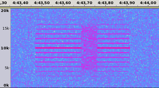
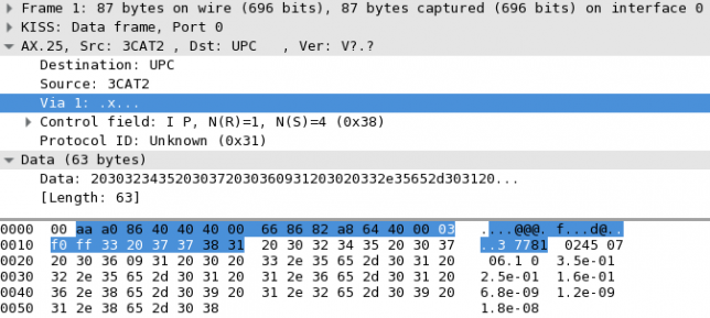
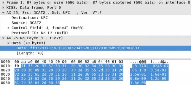
In a previous post, I looked at the telemetry packets transmitted by the satellite 3CAT-2. This satellite transmits 9600bps AX.25 BPSK packets in the Amateur 2m band. As far as I know, it is the only satellite that transmits fast BPSK without any form of forward error correction. LilacSat-2 uses a concatenated code with a (7, 1/2) convolutional inner code and a (255, 223) Reed-Solomon outer code. The remaining BPSK satellites transmit at 1200bps, either using AX.25 without FEC (the QB50p satellites, for instance), or with strong FEC (Funcube, for example). Therefore, I remark that 3CAT-2's packets will be a bit difficult to decode without errors. But how difficult? Here I look at how to use the theory to calculate this, without resorting to simulations.

The bit error rate of BPSK in an AWGN channel is known to be

P_b = \frac{1}{2}\operatorname{erfc}\left(\sqrt{\frac{E_b}{N_0}}\right).

Here, P_b is the probability that a bit is decoded erroneously, E_b is the energy per bit (in Joules), N_0 is the noise power spectral density (in W/Hz, which is the same units as Joules), and \operatorname{erfc} denotes the complementary error function, defined by

\operatorname{erfc}(x) = \frac{2}{\sqrt{\pi}}\int_x^\infty e^{-t^2}\,dt,

While E_b/N_0 is a useful parameter to compare different modems, when talking about signal strength it's more practical to use carrier to noise ratio, or C/N. Here C is the power of the signal (in W) and N is the noise power in the bandwidth B to which the signal is filtered (in W again). Therefore, for a bitrate b (in bit/s), the relation between these two parameters is

\frac{C}{N} = \frac{b}{B}\frac{E_b}{N_0}.

For the case of 3CAT-2, b = 9600\mathrm{bit/s} and B is about 15kHz.

Since AX.25 uses no form of error correction (it only uses CRC-16 error checking), all the n bits of the packet have to be received successfully. In an AWGN the bits are independent random variables, so the probability that the packet is received OK is

P_{\mathrm{OK}}=(1-P_b)^n.

For the case of 3CAT-2, the packets are 86 bytes long, including the AX.25 headers. To this, we have to add 2 bytes for the CRC and 2 bytes for each of the 0x7e flags marking the beginning and end of the packet, giving a total of 90 bytes. Thus, n=720\ \mathrm{bits}. In practice, n will be slightly larger than this due to bit-stuffing. We will ignore this difference, as the results are not very sensitive to the value of n.

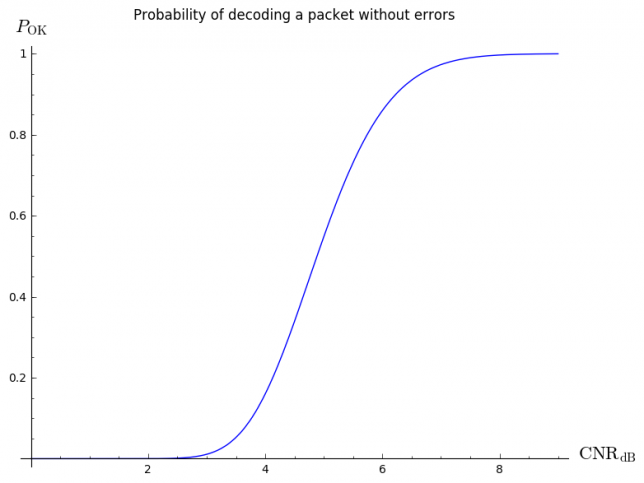
Using all these ingredients, we can plot the following curve.

cnr

You can see that the threshold for successful decoding is around 5 or 6dB CNR. This plot was done in Sage using the following code:

plot(lambda CNRdB:
     (1-0.5*pari(sqrt(15/9.6*10^(CNRdB/10))).erfc())^n,
     (x,0,9),
     axes_labels=["$\mathrm{CNR}_{\mathrm{dB}}$", "$P_{\mathrm{OK}}$"],
     title="Probability of decoding a packet without errors")

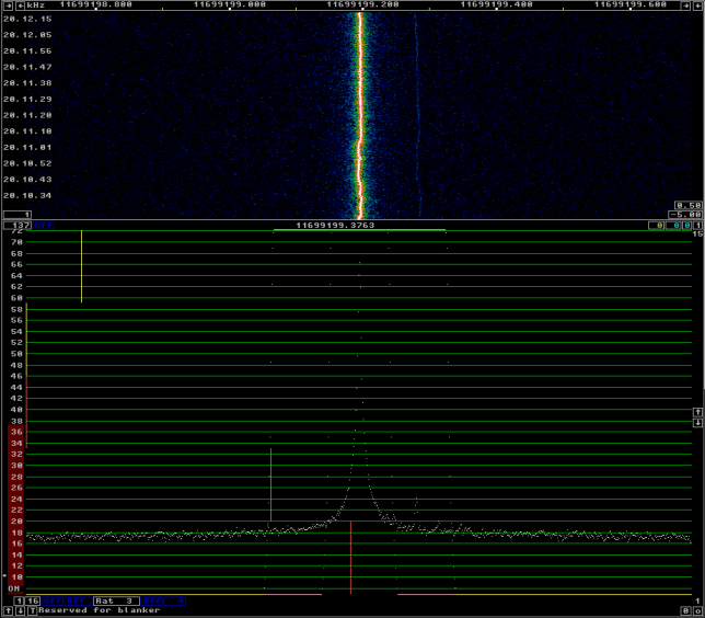
However, CNR is not an parameter which is easy measure directly. We are much more used to talk in terms of signal plus noise to noise ratio, or (S+N)/N. This is by how much the signal meter increases when receiving the signal versus when receiving only the noise floor. The relation between the two is straightfoward:

\frac{S+N}{N} = \frac{C}{N} + 1.

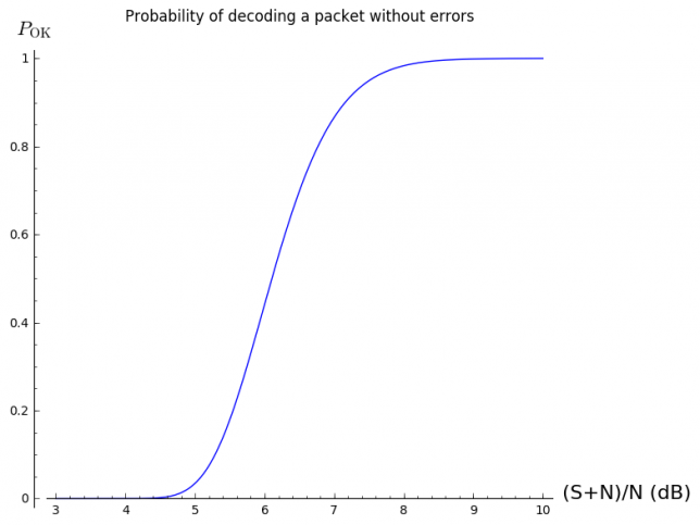
However, when writing this relation in dB's, it becomes a bit complicated and difficult to compute mentally. The rule of thumb is that a 3dB (S+N)/N corresponds to 0dB C/N (obvious), and that for high values (say greater than 10dB), both parameters are more or less the same. We can plot a similar curve in terms of (S+N)/N.

snr

You can see that the threshold for successful decoding is between 6 and 7dB (S+N)/N. This was done with:

plot(lambda SNNRdB:
     (1-0.5*pari(sqrt(15/9.6*(10^(SNNRdB/10) - 1))).erfc())^n,
     (x,3,10),
     axes_labels=["(S+N)/N (dB)", "$P_{\mathrm{OK}}$"],
     title="Probability of decoding a packet without errors")

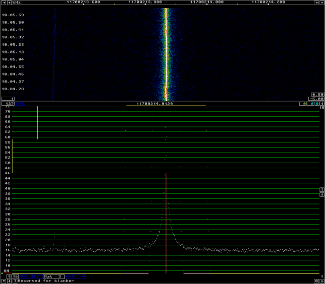
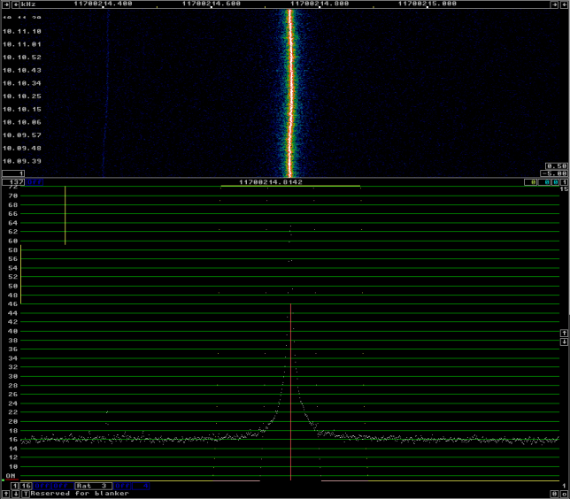
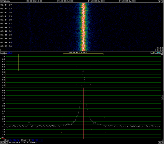
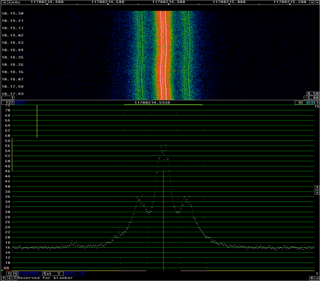
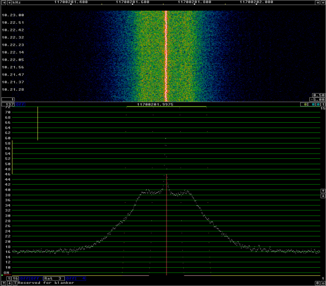
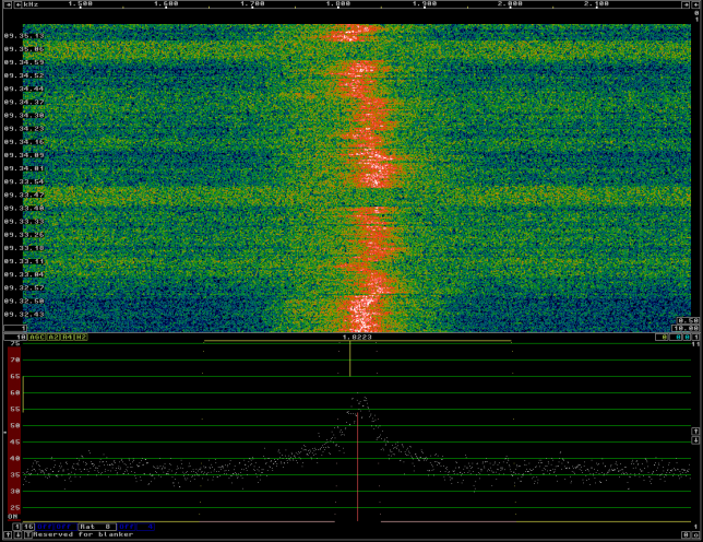
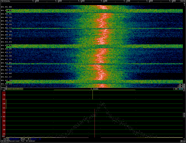
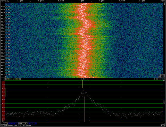
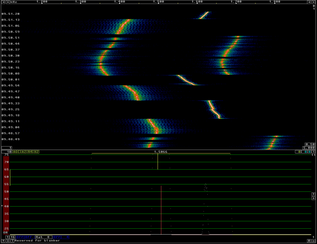
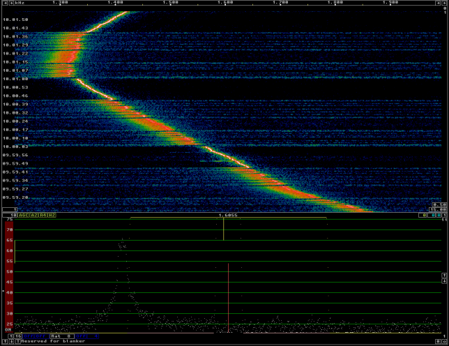
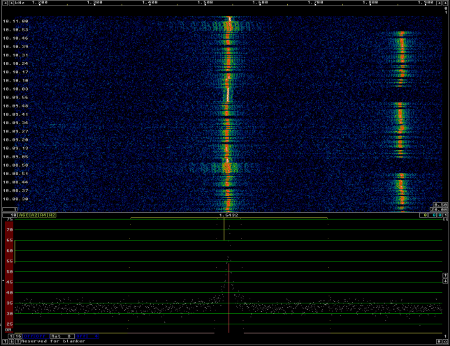
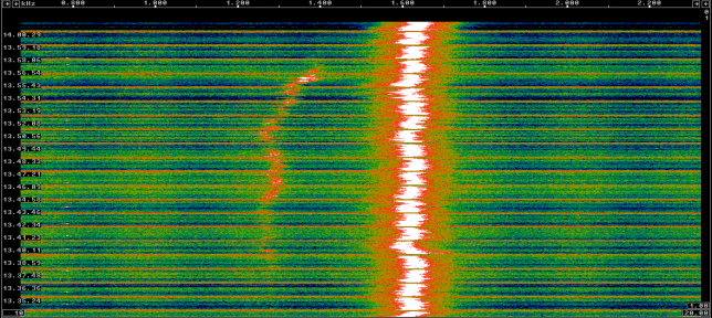
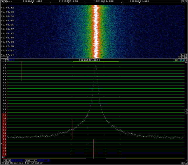
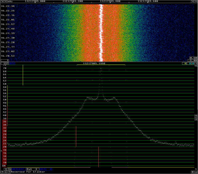
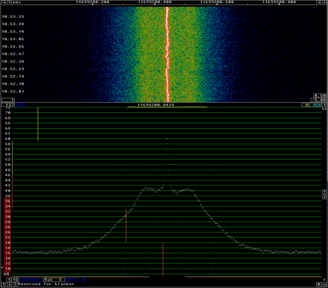
Although in reality the channel behaves worse than an AWGN channel (typically it can be modelled as a fading channel), the threshold around 6 or 7dB (S+N)/N matches up quite well with what I've seen in the recordings. The packet that I managed to decode from Scott K4KDR's recording was 7dB (S+N)/N. The remaining packets, which I couldn't decode, where 5dB (S+N)/N or weaker. In Jan PE0SAT's recording, there are several packets with (S+N)/N between 10dB and 15db, and I was able to decode 10 of these.

Almost everything that I've done here can be used for 1k2 AX.25 BPSK. Since both b and B scale down by the same factor of 8, the ratio b/B stays the same. The only difference is that N will scale down by a factor of 8, or -9dB. Thus, to achieve a particular value of CNR or (S+N)/N, the 1k2 signal can be 9dB weaker than the 9k6 signal. Of course, this is a huge difference.

However, to put things into perspective, one has to remember that there are plenty of 9k6 or faster AX.25 FSK satellites working, many of which are easy to receive. As this image shows, for a given bit error rate, BPSK is about 2dB better than FSK, so a 9k6 AX.25 BPSK modem can work fairly well for a VHF or UHF satellite.

Telemetry format of 3CAT-2

$
0
0

The team from the NanoSat Lab in Universidad Politècnica de Catalunya have published a telemetry analyser for 3CAT-2. This analyser is designed to connect to a TCP server and get the AX.25 frames in KISS format.

The telemetry format is rather simple, as one can see by looking at the PrintBeacon() function in 3cat2_telemetry.c. As I imagined, the contents of each beacon are just the numerical values of several telemetry channels written in ASCII. For example:

3 7781 0245 07 06	1 0 3.5e-01 2.5e-01 1.6e-01 6.8e-09 1.2e-09 1.8e-08

All the fields are separated by a space, except the 5th and 6th fields, which are separated by a tab. The content of the first 7 fields is as follows:

  1. Mode. Possible values: 1 survival mode, 2 sun-safe mode, 3 nominal mode, 4 TX communication incoming (data downlink), 5 RX communications (command uplink), 6 and 7 payload mode.
  2. Battery voltage in mV. In the example 7.781V.
  3. Current consumption in mA. In the example 245mA.
  4. EPS temperature (probably in ºC). In the example 7ºC.
  5. Antenna temperature (probably in ºC). In the example 6ºC.
  6. Status of the ADCS system. 0 means detumbling enabled. 1 means SS-nominal.
  7. Control flag of the ADCS routine. Possible values: 0 automatic, 1 manual

The next 3 fields are floating point numbers. If detumbling is enabled, they correspond to magnetomer values in nT for the axes X, Y and Z respectively. If detumbling is not enabled, they correspond to the sun vector, axes X, Y and Z.

The last 3 fields correspond to the control voltages for axes X, Y and Z, regardless of whether detumbling is enabled or not.

Of course, the telemetry format is so easy that it can even be parsed with a "one-line" awk script:

 strings sats/3cat2-20160824-pe0sat.kiss | awk '{if ($1==1) printf "Survival"; if ($1==2) printf "Sun-safe"; if ($1==3) printf "Nominal"; if ($1==4) printf "TX"; if ($1==5) printf "RX"; if ($1>=6) printf "Payload"; printf "  %.2fV  %dmA  EPS: %2dºC  Ant: %2dºC  ", $2*1e-3, $3, $4, $5; if ($7==0) {printf "ADCS auto  "} else {printf "ADCS manual  "}; if ($6==0) {printf "Detumbling  (%f,%f,$f) nT", $8, $9, $10} else {printf "SS-nominal  Sun: (%.2f,%.2f,%.2f)", $8, $9, $10}; printf "  Control (%.1e,%.1e,%.1e)V\n", $11, $12, $13}'

which shows the following output:

Nominal  8.26V  233mA  EPS:  4ºC  Ant:  8ºC  ADCS auto  SS-nominal  Sun: (0.49,0.42,1.00)  Control (6.9e-09,1.7e-09,1.7e-08)V
Nominal  8.28V  221mA  EPS:  5ºC  Ant:  8ºC  ADCS auto  SS-nominal  Sun: (0.16,0.87,0.57)  Control (6.7e-09,1.4e-09,1.7e-08)V
Nominal  8.29V  245mA  EPS:  5ºC  Ant:  8ºC  ADCS auto  SS-nominal  Sun: (0.26,0.96,0.46)  Control (6.7e-09,1.4e-09,1.7e-08)V
Nominal  8.30V  257mA  EPS:  5ºC  Ant:  8ºC  ADCS auto  SS-nominal  Sun: (0.62,0.78,0.42)  Control (6.7e-09,1.4e-09,1.7e-08)V
Nominal  8.30V  257mA  EPS:  5ºC  Ant:  9ºC  ADCS auto  SS-nominal  Sun: (0.64,0.72,0.49)  Control (6.7e-09,1.4e-09,1.7e-08)V
Nominal  8.30V  245mA  EPS:  5ºC  Ant:  9ºC  ADCS auto  SS-nominal  Sun: (0.64,0.66,0.59)  Control (6.8e-09,1.5e-09,1.7e-08)V
Nominal  8.30V  245mA  EPS:  5ºC  Ant:  9ºC  ADCS auto  SS-nominal  Sun: (0.60,0.60,0.71)  Control (6.8e-09,1.5e-09,1.7e-08)V
Nominal  8.30V  245mA  EPS:  5ºC  Ant:  9ºC  ADCS auto  SS-nominal  Sun: (0.54,0.54,0.86)  Control (6.8e-09,1.6e-09,1.7e-08)V
Nominal  8.29V  245mA  EPS:  5ºC  Ant: 10ºC  ADCS auto  SS-nominal  Sun: (0.45,0.49,1.00)  Control (6.9e-09,1.7e-09,1.7e-08)V
Nominal  8.28V  245mA  EPS:  5ºC  Ant: 10ºC  ADCS auto  SS-nominal  Sun: (0.32,0.44,1.00)  Control (6.9e-09,1.7e-09,1.7e-08)V

The KISS file in question was obtained from the recording by PE0SAT that I mentioned at the end of a previous post.

Many thanks to Juan Fran Muñoz and the rest of the NanoSat Lab team for publishing the telemetry analyser and sharing details about the satellite and the operations.

Introducing gr-satellites

$
0
0

This post is to present my gr-satellites project. The goal of this project is to make a collection of GNUradio decoders for the telemetry of different satellites. The decoders support submitting telemetry in real time to the PE0SAT telemetry server. Another goal is that the decoders are as easy to use as possible, to try to make more people interested in receiving digital telemetry from satellites and collaborating in online telemetry submission.

The decoders can be used with the Gqrx SDR software, using its UDP audio streaming capabilities. This is the easiest way to use the decoders. It is also possible to use the GNUradio frontends in the companion project gr-frontends. These support several different SDR hardware, WAV and IQ recordings, and conventional receivers connected through a soundcard. They are design to be flexible and to allow its use in headless and automated receiving configurations.

The long-term goal of this project is to provide an alternative software chain to the UZ7HO soundmodem, AGW packet engine and DK3WN telemetry forwarder. The use of GNUradio makes these decoders more configurable and flexible and eases programming decoders for non-AX.25 satellites, which usually employ strong forward error correction.

Currently, the satellites supported by gr-satellites are 3CAT-2, AAUSAT-4 and GOMX-3. I plan to continue adding support for more satellites in the future.

IARU R1 145MHz contest

$
0
0

Today I hiked with all the family to La Najarra, SOTA summit EA4/MD-013 (2122m), to participate in the IARU Region 1 145MHz contest. Unfortunately, for some weird reason very few stations in Spain participate in this contest. My plan was to make a combined contest activity and SOTA activation, making QSOs with whoever was working SSB in the contest, but spending most of the time calling in FM. This gives me the opportunity to contact many more stations, because not many hams have a VHF yagi and SSB radio, but many have a VHF vertical and FM radio. It also gives these local hams the possibility to work a SOTA summit (most SOTA activity is in HF here) and work some DX with a quite basic FM station (100km or more are easy to achieve).

I worked from around 9:30UTC to 11:30UTC. The station was, as usual, an FT-817ND with 5W and an Arrow satellite yagi (3 elements).

I've put in the contest log all stations that were able to give me their locator (many hams that work only FM have no clue about what locators are). This is OK with the contest rules. The other stations went only to the SOTA log. Below, you can find the map of contest contacts. I made a total of 17 contacts, but, of course, I can't put on the map the stations that didn't know their locator.

HORYU-4 CW telemetry format

$
0
0

HORYU-4 is a small satellite from Kyushu Institute of Technology (Japan) designed to test a high voltage solar array in space and observe the effects produced by the charge on the spacecraft due to the high voltage. It transmits telemetry on the 70cm and 13cm amateur bands. It has a CW beacon at 437.375MHz, a 1200baud AFSK telemetry downlink at 437.375MHz and a 100kbaud BPSK telemetry downlink at 2400.3MHz. The digital telemetry downlinks are only active over Japan and use a custom packet format. Here we take a brief look at the format of the CW telemetry.

There is available a CW telemetry format document from Kyushu. Unfortunately, this document is a bit incomplete and the information it contains is not enough to completely decode the CW telemetry. In this post I will give the full details together with a worked example.

The CW beacon from HORYU-4 starts with the callsign "JG6YBW HORYU4", which is followed by 21 hexadecimal digits. These encode the telemetry values. The CW beacon example below was extracted from a recording made on 2n May 2016 which was kindly provided by Yoshimoto JA6PL.

HORYU-4 CW beacon
HORYU-4 CW beacon

The telemetry message in this example is

 FABC11108387B6869801E

The analog telemetry values are encoded as an unsigned 8bit integer, which is read as two consecutive hexadecimal digits (the first digit represents the most significant part). The value of this integer from 0 to 255 is mapped to the telemetry value by means of a "linear scale" that is different for each telemetry channel. The minimum and maximum values of each channel (which correspond to 0 and 255) are not written anywhere in the telemetry format document. However, it is easy to reverse engineer these values using Mike DK3WN's decoder software.

The telemetry values are encoded as follows:

  • Digits 1 and 2. Battery voltage. Value from -393.19mV (00) to 8860.72mV (FF). FA = 8679.27mV.
  • Digits 3 and 4. Battery current. Value from -3710.14mA (00) to 1706.05mA (FF). BC = 282.97mA.
  • Digits 5 and 6. Battery temperature 1. Value from 0ºC (00) to 298.9ºC (FF). 11 = 19.93ºC.
  • Digits 7 and 8. Battery temperature 2. Value from 0ºC (00) to 298.9ºC (FF). 10 = 18.75ºC.
  • Digits 9 and 10. S-band antenna temperature. Value from -150ºC (00) to 148.9ºC (FF). 83 = 3.55ºC.
  • Digits 11 and 12. 1k2 TX temperature. Value from -150ºC (00) to 148.9ºC (FF). 87 = 8.24ºC.
  • Digits 13 and 14. Board temperature. Value from -150ºC (00) to 148.9ºC (FF). B6 = 63.33ºC.
  • Digits 15 and 16. 9k6 TX temperature. Value from -150ºC (00) to 148.9ºC (FF). 86 = 7.07ºC.
  • Digit 17 bit 1. Share memory. 1 = normal, 0 = trouble. In this case, normal.
  • Digit 17 bit 2. Reservation command. 1 = reserve, 0 = nothing. In this case, nothing.
  • Digit 17 bit 3. Operation mode. 1 = mission, 0 = nominal. In this case, nominal.
  • Digit 17 bit 4. Kill switch main. 1 = normal, 0 = kill. In this case, normal.
  • Digit 18 bit 1. Kill switch main. 1 = normal, 0 = kill. In this case, normal.
  • Digit 18 bit 2. Solar cell X. 1 = sunshine, 0 = shadow. In this case, shadow.
  • Digit 18 bit 3. Solar cell +Y. 1 = sunshine, 0 = shadow. In this case, shadow.
  • Digit 18 bit 4. Solar cell -Y. 1 = sunshine, 0 = shadow. In this case, shadow.
  • Digit 19 bit 1. Solar cell +Z. 1 = sunshine, 0 = shadow. In this case, shadow.
  • Digit 19 bit 2. Solar cell -Z. 1 = sunshine, 0 = shadow. In this case, shadow.
  • Digit 19 bit 3. SW_AODS. 1 = onf, 0 = off. In this case, off.
  • Digit 19 bit 4. MUX_OBO. 1 = onf, 0 = off. In this case, off.
  • Digit 20. Hours since restart (as a 4bit unsigned integer). In this case, 1 hour.
  • Digit 21. Operation mode (see values below). E = nominal.

The possible values of the operation mode are:

  • 0. HVSA "Discharge count or I-V measurement".
  • 1. HVSA + OBO "Simple waveform capture + counter" or "Full Waveform Capture + Counter".
  • 3. HVSA + OBO + AVC "Simple Waveform Capture + AVC + Counter" or "Full Waveform Capture + AVC + Counter".
  • 5. HVSA + VAT + OBO "Waveform Capture + Counter".
  • 6. HVSA + VAT + OBO + AVC "Waveform Capture + AVC + Counter".
  • 7. AVC "AVC Reference Picture Mode".
  • 8. DLP, PEC "Normal Measurement".
  • 9. DLP + HVSA, ELF + HVSA, VAT + HVSA "Measurement with High Voltage Source".
  • A. CAM "Timer, Target, Normal Mode".
  • B. SNG.
  • C. S-band downlink.
  • D. S-band processing.
  • E. Nominal.
  • F. Processing satellite.
Viewing all 500 articles
Browse latest View live