Quantcast
Channel: destevez – Daniel Estévez
Viewing all 500 articles
Browse latest View live

Scanning Ku band satellites with the FUNCube Dongle

$
0
0

I've recently installed my satellite dish and modified LNBF in my garden. This equipment will be used to receive Es'hail 2, the first geostationary satellite carrying an amateur radio transponder. Here I'll look at the hardware I'm using, how I did the alignment to the 25.5ºE geostationary orbital position where Es'hail 2 will be located, and how to have some fun scanning the direct broadcast satellites in the Ku band with a FUNCube Dongle Pro+.

The dish I'm using is a 95cm offset dish from diesl.es. It has an offset angle of 26º and a F/D of 0.5. This is probably the largest dish I could get very inexpensively, since the 110cm dish already costs 50% more. Using a gain calculator, this dish has a gain of 38.4dB at 10.5GHz. According to the preliminary link budget calculations, this is more than enough to receive Es'Hail 1 from my location, because the aim is for 75cm dishes to be usable in rainy areas at end of coverage, such as Brazil.

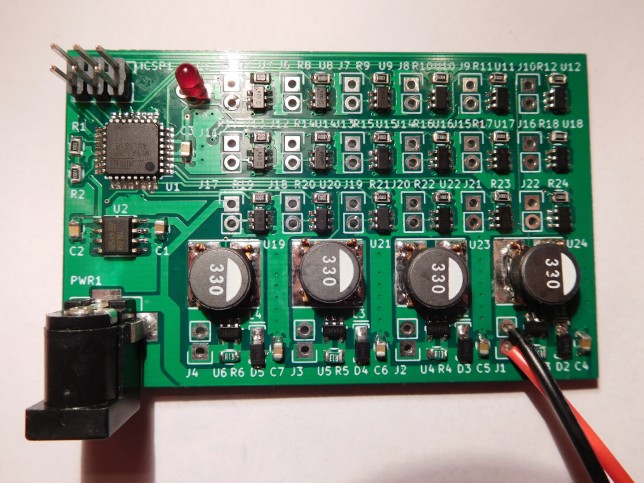
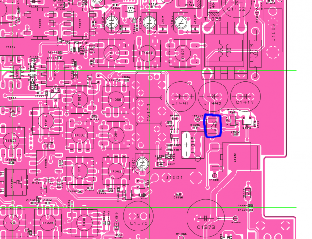
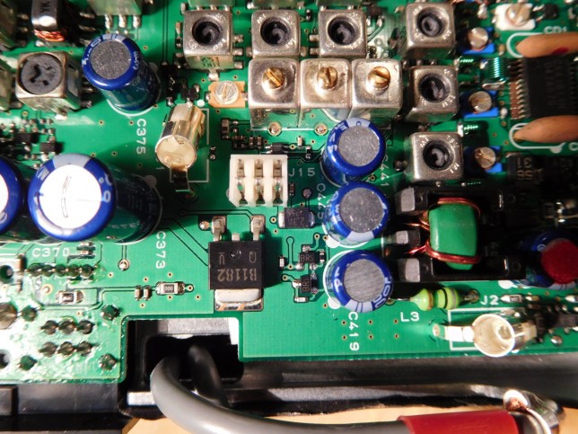
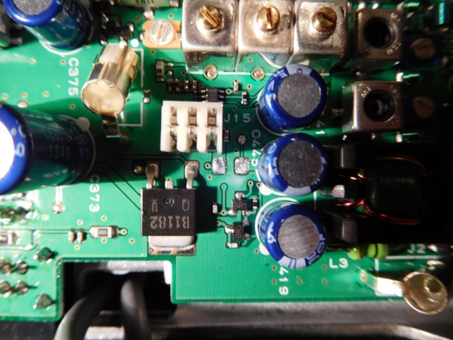
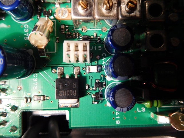
The LNBF I'm using is an Avenger PLL321S-2. I've removed its 27MHz crystal and installed a BNC connector to feed an external reference clock. I'm generating the 27MHz clock with the OCXO/Si5351A kit that I built recently. Although this kit includes a 27MHz OCXO, I'm using the Si5351A to generate the 27MHz reference, since this chip already outputs a 50 Ohm impedance signal. I intended to build a buffer amplifier to take the 27MHz signal directly from the crystal oscillator to get lower phase noise. However, the first designs of the buffer amplifier I built didn't work very well, and it seems that the phase noise from the Si5351A is adequate. Also, using the Si5351A allows me to feed a clock different from 27MHz to change the IF, although I probably won't need to do this, because I plan to use either an RTLSDR or a FUNCube Dongle Pro+.

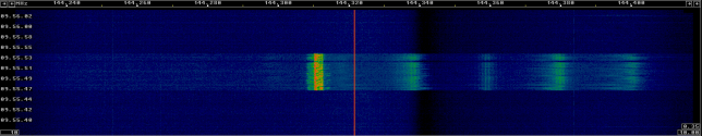
I have aligned the dish to the 25.5ºE geostationary orbital position, which is where Es'hail 2 will be located. To do the dish alignment, I used the following method. I used an RTLSDR to receive the signal of one of the DVB-S/DVB-S2 channels which are broadcast by Es'hail 1, which is also on the 25.5ºE position. Of course, the DVB-S signal is about 20MHz wide and the RTLSDR is only 2.4MHz wide so this signal is just received as an increase in the noise floor in all the passband (actually, depending on the modulation you can see some pattern in the signal for some channels). Then I used x11vnc and a VNC client on my Android phone to connect to my computer remotely. In this way, I could move the dish and look at the signal on my phone. Then it is just a matter of moving the dish to peak the signal. I haven't been very careful in doing the alignment, so I reckon I could get about 1dB more by doing the alignment more carefully.

The thing with this method is that you have to know the frequency and polarization of one of the DVB-S channels. Also, it helps to start with the dish pointing towards the correct location. Otherwise you risk to pick up a different satellite which broadcasts on the same frequency. To do this pre-alignment, I just waited until the sun was in the same azimuth as the satellite and the I looked at the shadow of the LNBF to point the dish towards the sun. Elevation can be also preset, since many dishes have an elevation scale which already accounts for the offset angle. However, this is not so important. If you have the azimuth more or less set, then you can just swing the dish up and down slowly until you get some signal.

To get the frequency of one of the DVB-S channels broadcast by Es'hail 1, one can use any of the different web pages which are devoted to listing this information. For instance, see the listing by SatBeams. The problem with these listings is that they're only up to date for popular satellites, so one cannot trust very much that the information is current. With the 25.5ºE position there is also the problem that the 26ºE position, which is near enough, has several Arab direct broadcast satellites broadcasting in the Ku band. Thus, one has to be careful to identify to which of the satellites the signals correspond, because the 26ºE position can be received without problems with the dish pointing to Es'hail 1.

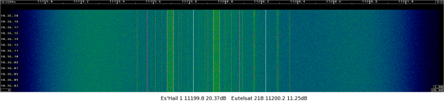
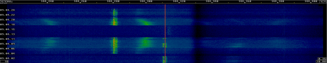
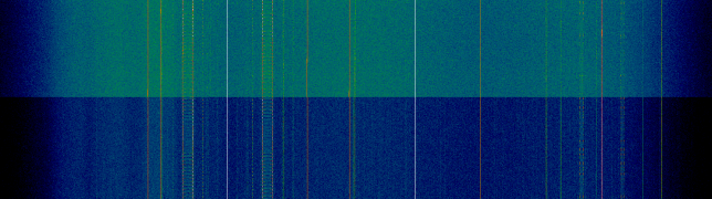
These considerations suggest the idea of plotting the frequency spectrum to get an idea of which satellites and frequencies we are receiving. I've used the FUNCube Dongle Pro+ instead of an RTLSDR because the FUNCube Dongle can receive across all the L band. To do the frequency scan, I've used FUN_Sweeper, which does exactly what I wanted: scan the power of a large chunk of spectrum and output it to a csv file. Probably another software could also be used, or I could program my own, but I just wanted some quick solution.

I have put the raw data on gist and used MATLAB to plot it.

25.5ºE Ku band scan

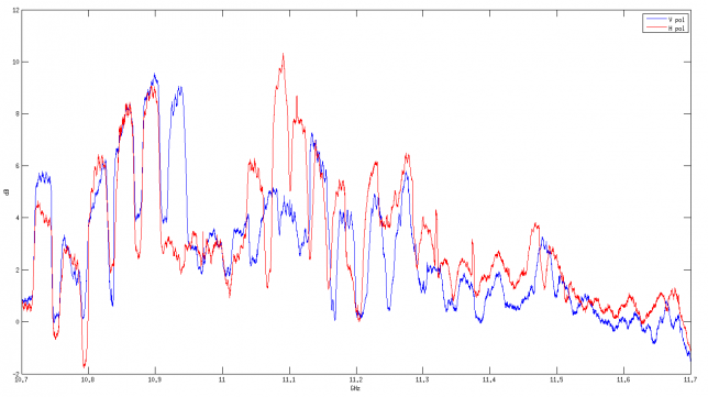
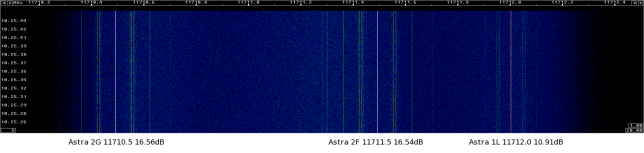
It seems that there are some problems for frequencies above 11.3GHz. Perhaps this is due to the bias tee I'm using to feed DC to the LNBF. I use just a simple inductor as an RF choke to block RF from flowing back into the power supply. Probably this inductor doesn't behave as a proper inductor for high frequencies in the L band.

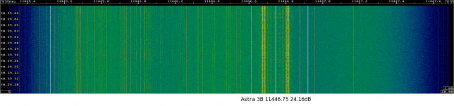
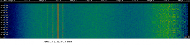
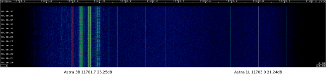
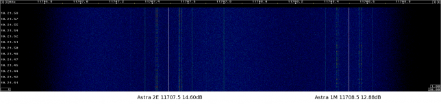
The signals in the lower part of the spectrum correspond to 5 DVB-S/DVB-S2 channels in the horizontal polarization and 6 DVB-S/DVB-S2 channels in the vertical polarization which are broadcast by BADR-5 from the 26ºE position. Arabasat has a nice channel listing where you can see the channels broadcast by the BADR satellites. Probably this information can be trusted to be current.

Es'hailSat doesn't have a good channel list, so the best strategy I have found to see what is currently broadcast by Es'hail 1 is to search for news of new channels in that satellite. Then I can go and check that this frequency is not used by any of the BADR satellites in 26ºE and if I receive something there I can have some confidence that it is transmitted by Es'hail 1. The news I've found are the following.

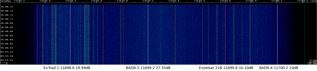
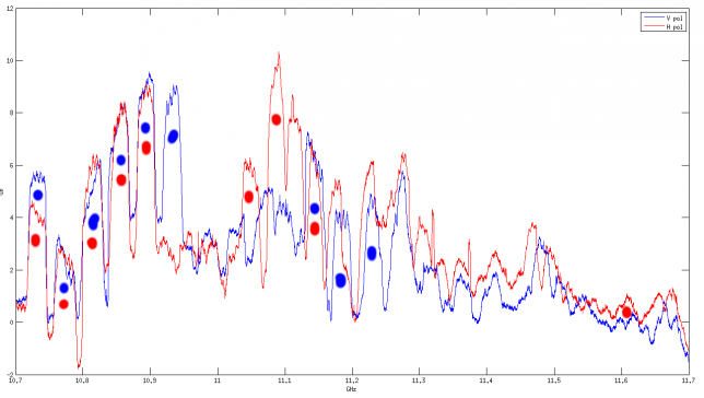
Al Jazeera HD is on 11045MHz horizontal polarization. Al Rayyan 2 is on 11142MHz vertical polarization. Al Araby is on 11142MHz horizontal polarization. All these three channels appear in my plot. Al Jazeera is on 11604MHz horizontal polarization. There is a small bump at this frequency in my plot, but I shouldn't trust that this part of the spectrum is accurate due to my setup.

Other channels in the plot that I have been able to identify are the following: 11228MHz vertical polarization (BADR-5). 11084MHz horizontal polarization and 11180MHz vertical polarization, which seems to be beIN on Es'Hail 1 according to SatBeams and LyngSat.

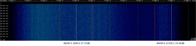
I've marked in the plot the channels I've been able to identify. As you can see, there are several signals which I could not identify. Perhaps I can use a DVB-S2 receiver to try to see what is on these frequencies.

Identified channels
Identified channels

A final remark is that today it is raining a little. It would be interesting to get scans on clear weather and on a really rainy day to try to see the effects of rain in the propagation.


Arduino LED driver: prototype finished

$
0
0

Today I've finished my prototype of the Arduino LED driver. I had already soldered and tested all the components quite a while ago, but I ran out of connectors for the LED strings, so I had to wait for more to arrive from China.

This project uses an Arduino-compatible ATmega328P and is able to drive up to 18 regular LED strings using the BCR420UW6 linear driver and 4 high-power LED strings using the AL8808 switching driver. The intended application is programmable lightning, such as Christmas or party lights.

PCB front
PCB front

PCB back
PCB back

The project is designed to run from an external 12V supply. However, it supports up to 30V if properly rated capacitors are installed, so feeding 24V or so may be a better idea if one intends to use longer LED strings. The ATmega328P is run from a L78L05ACD 5V 0.1A linear regulator. No external crystal or resonator is included, so the 328P is supposed to run using its internal oscillator. The only external communication included is an ISP port to program the microcontroller. This may be used to interface to other devices over SPI. However, one loses the ability to run 3 of the linear LED drivers, since all of the 328P I/O pins are used in this project.

A 100Ω external resistor is used with the BCR420UW6 for a typical LED current of 20mA. A resistor of a different value can be used for a LED current of up to 350mA, but for high currents there can be thermal issues (it's clearly impossible to run all the 18 drivers at 350mA). The AL8808 uses a current shunt of 130mΩ, which gives a nominal current of 770mA. A 33uH inductor and a DFLS240L diode are used with this switching regulator.

All resistors and capacitors are 0805, which is quite easy to solder by hand. The ATmega328P is a TQFP-32, which can be soldered by hand using the technique of drag-soldering. The AL8808 is a SOT-25. The two pins in one side can be soldered individually and the other three pins can be drag-soldered. The BCR420UW6 is a SOT-26. Both sides of this chip can be drag-soldered. The 5V regulator is a SOIC-8, so its pins can be soldered individually. Perhaps a smaller footprint for the regulator would have been nicer. The 3mm LED is just a power indicator that runs from the 5V rail.

The project doesn't specify connectors for the LED strings, so different types of connectors may be used or the LED string can be soldered directly for the PCB. The footprint in the PCB is for a standard 2x1 0.1'' pitch header. I'm using JST RCY connectors in this prototype, as that's what I already have in my LED strings.

I made two mistakes while building this prototype. The first was that the footprint for the DFLS240L was included backwards in the PCB, due to a pin numbering issue. I have a batch of 10 PCBs with this problem, but it is something minor, because the diode can be soldered in the correct orientation without much effort (but one has to pay some attention). The other mistake was specifying and soldering 100kΩ external resistors instead of 100Ω for the BCR420UW6's (a keen eye will spot that mistake on the picture above). I only noticed that while writing this post, but replacing them has being easy.

This project is Open Source Hardware. I've uploaded the Kicad project files to GitHub. I have spare parts that can be used to build this project, so I'm offering them as a kit.

Concurso Costa del Sol V-UHF 2016

$
0
0

Yesterday, my father and I hiked to Cerro de San Pedro, SOTA summit EA4/MD-020 (1425m), to work QRP in this month's national V-UHF contest: Concurso Costa del Sol. Since the forecast for Sunday was rainy, I decided to go up on Saturday's afternoon. The summit is a short hike from a nearby road. We arrived to the summit around 14:25UTC, so I could work in the contest for a bit more than two hours until we started packing at 17:00UTC before it got too dark.

Activity seemed a little low, although this is not surprising, given that the national RTTY contest was also running at the same time. I also get the impression that there is more activity on Sunday mornings. Nevertheless, my results have been better than in March's contest. I did fewer QSOs, but got more points and worked more DX. In fact, I could work almost everybody I heard. In the map below, as always, my location is marked in red, the stations in blue are those worked only in 144MHz and the ones in green where worked both in 144MHz and 432MHz.

The equipment I used was the usual: an FT-817ND and the arrow satellite yagi (3 elements on 144MHz and 7 elements on 432MHz). I had solved all the little problems that appeared during the previous contest, and everything worked just fine.

The only problem I had this time was reduced output power on 432MHz according to the FT-817ND's power meter. I'm now looking into this issue, but this problem could have existed for months, because it's probably being a long time since I last checked this. However, it wasn't much of a problem. The radio was probably putting out at least one or two watts. Of all the stations that I worked on 144MHz and had 432MHz, I only failed to work on 432MHz one, EB3JT, and it was because I could barely hear them on this band.

Me working from the summit

When we reached the summit, we found a little surprise: some kind of radio station is installed there. You can see it behind me in the picture above. The installation consists of a tower which is several meters high, a vertical antenna on top of it (perhaps some collinear antenna) and a small UHF yagi in the vertical polarization towards the bottom of the mast (if I recall correctly, it is three elements and points towards the south-west). Everything seems to run from three large solar panels and all the equipment is housed in a concrete structure. This station made some amount of QRM both on 144MHz and 432MHz. It could be heard as broadband noise almost all the time. Nothing too terrible, because the noise seemed to be vertically polarized, but a bit annoying nevertheless. I wonder what's the purpose of this station. I've tried to look it up on the Internet, but so far I've found nothing. Perhaps it's related to the railway service, as a long tunnel for the AVE Madrid-Segovia-Valladolid high-speed train runs below the mountain. The railway track for this line can also be seen in the picture above.

Replacing the fuse F1002 in the FT-817ND

$
0
0

On last Saturday's V-UHF contest I observed reduced output power on the 70cm band in my FT-817ND. I spent the next day poking inside the radio with the oscilloscope trying to see where the problem was. While doing this, at some point I completely lost output power in all bands. I found that the problem was that F1002, an SMD fuse, had gone open. Here I describe said fuse and the replacement procedure, which I found much easier than I thought.

As you can see in the schematic below, F1002 is connected between J1015, a board-to-board connector that goes to the PA board, and the trace marked in red, which runs almost directly to the DC input and battery connector. The purpose of J1015 is to provide 13V to the PA board. Hence, no wonder that with F1002 open the PA didn't work at all. This fuse is there so that it will blow if something goes terribly wrong in the PA board, in order to prevent further damage. According to the FT-817ND service manual I have, F1002 is installed only in lots 75 and later. In previous lots, the red trace runs directly from the line filter T1035 to the connector J1015 without any fusing. One should be a bit careful with this version of the service manual, as it is rather old (copyright 2005). In fact, my FT-817ND is marked with lot 35 (third and fourth digits in the serial number), so probably they ran out of lots numbers at some point and started again. I have been unable to locate a newer version of the service manual.

Location of F1002 in the schematic

F1002 is a Rohm semiconductor ICP-S2.3TN circuit protector. This is a 2.3A SMD fuse designed to blow quickly and protect ICs and related circuits. The manufacturer gives a typical internal resistance of 0.026Ω and the fuse is rated up to 50V.

The picture below marks the location of F1002 on the PCB. It is easy to spot, as J1001 and J1002 are the coaxial connectors with pigtails running down to the PA board for the RX and TX paths respectively. To access the component more easily, it is better to disconnect these pigtails. This is achieved by pulling carefully.

Location of F1002 on the PCB

The picture below shows F1002 with the pigtails already disconnected.

Original fuse F1002
Original fuse F1002

Removing the component was much easier than expected. Since this fuse conducts a fair amount of current, the traces are large and act as a good heatsink, so one has to use high temperatures on the soldering iron. Then one risks damaging the PCB if things are not done carefully. I used the technique of heating alternatively each of the pads with the soldering iron tip while pulling gently with some tweezers. First one of the pads came loose and then the second one. After removing the fuse, I tried to reflow the solder remaining on the pads to leave a smooth surface, but it needed very high tip temperatures. As you can see in the picture below, the result was quite nice.

Fuse F1002 removed
Fuse F1002 removed

It seems that the ICP-S2.3TN is quite hard to get, even in large quantities, as it is obsolete and out of production. I decided that almost any SMD fuse would serve as a replacement, and I wanted to fix this problem as soon as possible, so I looked at what SMD fuses my local electronic store had in stock. I decided for the 1206SFF200F/63. This is a 2A fuse in a 1206 footprint. I eyeballed that a 1206 component would fit nicely and the lower current rating shouldn't be much of a problem. The voltage rating for this fuse is 63V and its resistance is 0.050Ω. It also blows as fast as the ICP-S2.3TN. It's not the perfect replacement, but it can do the job.

The picture below shows the new fuse soldered in place. It is an ugly, unmarked component. To solder it, I used the technique of tacking one pad, then soldering the other one, and finally applying more solder to the first pad. It was quite hard to get the solder to flow and high temperatures were needed. I used the help of large amounts of flux, which not only helps the solder flow, but it also helps transmit heat when it starts boiling. Finally, I cleaned the area with isopropanol and a cotton swab.

Replacement fuse installed

I don't know why this fuse went open. It is possible that while poking around with the oscilloscope probe, I shorted something accidentally. However, the fused 13V net is only present in the main board in this fuse and in the connector J1015. Then it runs off to the PA board, which was covered with the bottom case. Hence, I think it is unlikely that I shorted this 13V net to ground, as I wasn't probing anywhere near J1015 and I didn't notice anything weird.

After replacing the fuse, the problem of reduced power output in the 70cm band still persists. However, I think I just need to do a software calibration and increase the TX gain in this band a little. I need a power meter to do this properly, so I will talk about it in a future post.

Adjusting TX gain in the FT-817ND

$
0
0

If you've been following my latests posts, you'll know that during the last V-UHF contest I detected reduced output power on the 70cm band in my FT-817ND. The output power was only about 60% of the maximum 5W in SSB and CW, but in FM mode it reached 5W. This problem only happened on the 70cm band. On all the other bands, the radio reached 5W output power in every modes. After spending some time studying the service manual, I came to the conclusion that the problem was that TX gain in the UHF band was too low. This is a software calibration parameter, so, in the end, fixing this problem has been rather easy.

Below you can see the relevant part of the block diagram of the FT-817ND. Q1007 is marked in blue. This is an IF amplifier where the FM signal and the signal for SSB and CW join together. Before this stage, the FM signal and the SSB/CW signals follow totally different paths. Q1007 is a dual gate FET. The ALC circuit applies a DC level to its second gate to control the gain of this stage. This ALC circuit is rather complex: it monitors output forward and reverse power and it will reduce the gain of Q1007 under high forward power or high SWR conditions. In fact, the ALC circuit is what limits the output power to 5W, since the finals of the FT-817ND can reach 10W or more.

The signal then passes to Q1002 (marked in green), which is an attenuator controlled by the software calibration parameter TX gain. This parameter is band-dependent (there are 3 HF bands plus VHF and UHF), but mode-independent. Then, the signal is mixed with the local oscillator to convert it to the transmit frequency, filtered and amplified before passing to the PA board.

FT-817ND TX gain & ALC chain

The key aspect to understand the problem with my radio is something that is not really mentioned in the manual: when reaching Q1007, the FM signal is at higher level than a (full power) SSB/CW signal. Thus, the FM mode will operate under a high level ALC action, which will reduce the gain of Q1007. Even if TX gain is set a bit low, the radio will reach full 5W output power, since the ALC will just reduce a its action to compensate for increased attenuation in Q1002. However, the SSB/CW mode operates under a low level ALC action. The ALC is just used to make the radio reach full output power even if the gain of the finals changes slightly under temperature variation (or similar). Therefore, if TX gain is set a bit low, the ALC level will drop to zero and the radio will not reach full output power. That is precisely the problem I was encountering. It seemed that I just had to adjust TX gain for the UHF band.

The service manual describes a procedure to adjust TX gain: A 1kHz 1mV signal should be injected into the microphone jack. Then TX gain should be adjusted so that the output power is 2.5W. However, this procedure wasn't so easy to do for me, because I would have to hook up a sound card to the microphone jack, and adjust the level of the injected signal using the oscilloscope to monitor. Also, this procedure relies on the correct SSB mic gain being set.

Instead, I used the following procedure. I assumed that the VHF band was more or less well adjusted and I took advantage of the fact that I have fldigi in my computer prepared to do digital modes and hooked up to the radio properly. I generated a 1kHz signal with fldigi and lowered the soundcard volume until the output power in VHF was about 3W (there is an unlabeled mark between 2W and 5W in the cheap power meter I'm using, so I just aimed for that mark). Then I switched to UHF and increased TX gain until the output power was the same as in VHF.

To adjust TX gain, I used FT-817 Commander instead of using the built-in software calibration mode (which is accessed by pressing A, B and C while powering on the radio). FT-817 Commander can read and update calibration parameters over CAT by reading and writing the EEPROM directly. Of course, this is a bit risky in case something weird happens with the serial connection, but it allows me to use the radio normally and adjust the calibration parameters with the computer. Before touching any of the parameters, you should take note of all the factory settings. I've made a gist with the factory settings for my radio.

I've found that the TX gain parameter is rather sensitive. The effect of varying this parameter by a single step is rather noticeable. Hence, it is not very important to use precission lab equipment to adjust this parameter. Even if the measurement error is very low, it will be impossible to adjust this parameter very precisely. In fact, in my case I only needed to increase TX gain from 56 to 58. After making this adjustment, the radio seems to be working properly.

Outputting the crystal oscillator directly in the Si5351

$
0
0

I'm using a OCXO/Si5351A kit as an external 27MHz reference for my LNBF-based 10GHz receiver. At first, I intended to use a buffer amplifier to take out directly the 27MHz cyrstal oscillator in the kit. However, I finally configured the Si5351A to generate 27MHz, as that was simpler.

Taking a look today at the documentation for the Si5351, I've realised that it is possible to configure the Si5351 to connect some of its outputs directly to the crystal oscillator input, acting as a buffer and bypassing all the frequency synthesis stages. To do this, XO_FANOUT_EN, which is bit 6 in register 187 "Fanout enable", must be set to 1. The selector CLKn_SRC, which is bits 3 and 2 of clock control register (registers 16-23), is set to 00 (XTAL source) on reset, so this is already set correctly. It is probably a good idea to set CLKn_IDRV to 11 to get the highest drive strength on the output pin.

First signals from AAUSAT-4

$
0
0

Today I woke up early to receive the signals from AAUSAT-4 as it passed over Spain for the first time. This satellite was launched from Kourou yesterday at 21:02UTC into a Sun-synchronous orbit. The main payload for the launch was Sentinel-1B, a 5GHz Synthetic Aperture Radar satellite from the Copernicus project of the ESA. The remaining satellites that were launched by the Soyuz rocket were Microscope, from the French CNES, designed to test Einstein's equivalence principle and the three cubesats in the Fly You Satellite! program: OUFTI-1, from the University of Liège, which carries a D-STAR amateur radio transponder, e-st@r-II, from the University of Torino, and AAUSAT-4, from the University of Aalborg, which carries an AIS receiver. Since the launch was into a polar orbit, the first pass of the Fly Your Satellite! cubesats over Spain was at 05:42UTC today.

I used a FUNcube Dongle Pro+ and a handheld Arrow Satellite antenna (a 7 element yagi on 70cm) to try to record the signals from AAUSAT-4 and e-st@r-II. The software used was Linrad, and my locator IN80DO. I have several buildings around my garden, but signals from AAUSAT-4 where quite strong (reaching 20dB over the noise floor) when the satellite was in clear view. e-st@r-II was not heard at all (and I haven't seen any reports of someone else receiving it, either).

The beacon format for AAUSAT-4 is well described on their webpage. The satellite beacons every 30 seconds, and one out of ten beacons is in 30wpm CW. The remaining beacons are in 2k4 FSK FEC coded CSP (the image below the title of this post shows a CSP packet in Linrad's waterfall). I managed to receive one CW beacon and several strong CSP beacons.

The CW beacon is the first thing I decoded after sending the reception report and IQ recording to the AAUSAT-4 team. Below you can see a spectrogram (done with Audacity). The beacon content was "OZ4CUB B8.0 T16+", indicating a battery voltage of 8.0V and a temperature of 16ºC.

CW beacon
CW beacon

One interesting thing I've noticed is that the frequency jumps a bit sometimes. Look carefully at the letters C, 8 and 0 in the image above. This can also be observed in CSP transmissions, but it is only noticeable during a long transmission.

Then I asked the satellite team if they had some software decoder for the CSP beacons. It turns out that they have some GNURadio custom blocks that may take some effort to get working but that definitely can be used to decode the beacons.

I did my own clock recovery and bit slicing routines in GNURadio, since I was already doing the signal filtering and FM demodulation in Linrad. You can see below my flowgraph. It's very similar to what is done in the decoder from the university. A small remark is that it pays off to set a relatively high value for the threshold in the Correlate Access Code block, because FEC can recover packets having many bit errors. The syncword used is OZ4CUB in ASCII. The signal is first multiplied by a constant to make it range between -1 and +1, which is what the clock recovery block expects to work optimally. The constant is negative because otherwise the bits are inverted for some reason.

GNURadio CSP beacon receiver

The results from the decoder are in gist. A total of 5 beacons could be decoded.

The first CSP packet I recorded was a long transmission lasting several seconds. Probably the satellite responding to some command from its ground station in Aalborg. The beacon decoder shows that this packet includes the contents for a normal beacon, but I haven't decoded the remaining data. You can see that the "packet sent" count went up by 10, so this long transmission was probably composed of 10 different CSP packets.

The IQ file for the recording can be downloaded from Google Drive. It is a wav file with 192kHz sampling rate. The centre frequency is 437.450MHz and the start of the recording is 2016-04-26 05:42:34UTC.

Receiving Ku-band geostationary satellite beacons

$
0
0

After sorting out some problems with several connectors which caused huge phase noise in the external 27MHz reference, I have my 10GHz receiver up and running as it should. This station will be used to receive Es'hail-2 in the future. The station is composed of a 95cm offset dish, an Avenger PLL321S-2 Ku-band LNBF modified to use an external 27MHz reference, an OCXO/Si5351A kit used as the 27MHz reference, an RTL-SDR, and a cheap DVB-S2 receiver as a power supply (this allows me to change polarizations and LO frequency easily).

The dish is pointing to the 26ºE or 25.5ºE orbital position, where Es'hail-2 will be. Actually, I have pointed the dish to peak the beacon from BADR-5 the best I can. To test the performance of the station, I have tried to receive the beacons from several Ku-band satellites. Here are the results.

A good reference to do this sort of experiments is the following beacon list. It also includes waterfall plots of many beacons, so sometimes you can identify a satellite not only by its frequency and polarization but also from the shape of its beacon in the waterfall.

The list of satellites heard is as follows (all with the dish pointing towards 26ºE):

  • 19.2ºE Astra 1N, Astra 1M, Astra 1L
  • 21.5ºE Eutelsat 21B
  • 23.5ºE Astra 3B
  • 25.5ºE Es'Hail 1
  • 26.0ºE BADR-5, BADR-6
  • 28.2ºE Astra 2F, Astra 2G
  • 28.5ºE Astra 2E

Below you can find the list of waterfall plots. It is recommended to click on each image to view it in full size. The signal strength is the signal to noise ratio of the beacon carrier in 500Hz bandwidth.

11200MHz H pol
11200MHz H pol
11446MHz H pol
11446MHz H pol
11453MHz V pol
11453MHz V pol
11699MHz H pol
11699MHz H pol
11699MHz V pol
11699MHz V pol
11702MHz V pol
11702MHz V pol
11708MHz V pol
11708MHz V pol
11711MHz V pol
11711MHz V pol

A bunch of data from AAUSAT-4

$
0
0

Recently, I have published a Gnuradio AAUSAT-4 decoder in Github. It is based on software from the university team, but several parts have been rewritten completely.

The current features of this decoder are as follows:

  • FEC decoding of both long frames and short frames using the code from bbctl (this code is included in the Gnuradio decoder)
  • CSP header parsing according to the specifications in Wikipedia
  • Parsing of the COM and EPS fields in telemetry beacons, using the code from the university team

In the future, I would like to be able to parse more data from the satellite, but I don't have the format specifications. I'm trying to get the university team to send me some information.

The basic information about the packet format used by AAUSAT-4 is listed in their website. However, there are certain things that are not explained so well. AAUSAT-4 can transmit two types of frames: long frames and short frames. Long frames are marked by the FSM byte 0x59 and contain 250 bytes of FEC, which after decoding yield 92 data bytes. Short frames are marked by the FSM byte 0xA6 and contain 128 bytes of FEC, which after decoding yield 31 data bytes. The first 2 bytes in these data are the length in bytes of the CSP packet (not counting its 4 byte CSP header). The length is stored as a big-endian unsigned 16-bit integer. The next bytes contain the CSP packet, and the last bytes are padding to obtain the full 92 or 31 data bytes. The FEC routines from bbctl handle this length field automatically, and they return just the CSP packet.

The first 4 bytes of the CSP packet are the CSP header. The last 2 bytes are an HMAC field. The HMAC implementation uses SHA-1, and only the first 2 bytes from the digest are used as the HMAC field. However, the key used by the satellite is unknown.

The code from the university team contains this information about the assignation of CSP addresses. This can be used to classify the packets.

ESP   = 0
FP    = 1
LOG   = 1
SWISS = 1
AIS2  = 3
UHF   = 4
ADCS1 = 5
ADCS2 = 6
MCC   = 9

Apparently, telemetry beacons should come from address 4 (UHF) and the destination address should be 9 (MCC), port 10. This seems to be the case.

Jan PE0SAT has a some IQ recordings from AAUSAT-4 that can be used to test my decoder. I'm using the flowgraph in examples/oz4cub-pe0sat.grc. I use gr-gpredict-doppler to do Doppler correction. Knowing that PE0SAT is in the locator JO21ho, the rest of the information, such as time and centre frequency is in the filename for the recording.

Today I have processed his recording from 20160428. This is still in 2400 bauds (I think they're running 9200 bauds now). You can find the decoding log from my software in Gist. In total, it is almost 10kB of data from the satellite. That is quite good, given that the team states in a post in the AAUSAT-4 blog today that they can download up to 20kB per pass. In this recording, the satellite only sends two brief streams of packets to the ground station.

As I don't have the details for the format of the data, I can't parse it. However, it is interesting to see which of this data is ASCII. If you look at the packets represented as python strings, you can see that there are several NULL-terminated ASCII strings inside some packets. A more close look reveals patterns such as this one:

Enabled on BAT1\x00fference 10\x008 mV\x00reading 679.\x00

It seems that these are the contents of some buffer where NULL-terminated strings have been stored on top of each other. The software is probably supposed to process only the first string it finds. I find this a quite curious.

Let's see what can we decode in the future. It would be really awesome to be able to decode some IQ data from the AIS receiver. I think this would be the first time that Amateurs get to play with IQ data from an SDR in space.

Concurso Segovia V-UHF

$
0
0

This weekend has being very rainy, so I haven't been able to participate in the national V-UHF contest with my usual portable setup. Instead, I have driven to the countryside just outside town and used the mobile antenna on my car to work in the contest from inside the car. This antenna is a 50cm vertical whip which is magnetically mounted on the roof of the car. Of course, due to the low gain and polarization mismatch, I am only able to work some local contacts with this antenna. In this way, I have been able to have a couple hours of fun this morning without getting wet.

As always, the map of stations worked below. My position is in red. Stations in blue where worked only in 144MHz. Stations in green where worked both in 144MHz and 432MHz.

One interesting and unexpected thing was that EA4GKQ was much stronger in 432MHz than in 144MHz. In 144MHz it was a bit difficult to copy him. In 432MHz he had a big signal, however. Apart from that, the contest went pretty much as expected with this setup.

Since I was going to be inside the car all the time, I could bring with me my FUNcube Dongle Pro+ to use it as a panadapter for the FT-817ND. Using it, I could locate activity very quickly. Also, I could see that some stations had signals which where far from clean. This is something I suspected from tuning around them with my FT-817ND in previous contests, but with an SDR, you can see it clearly in the waterfall. Below, you can see two stations with huge phase noise and one having a really wide SSB signal full of IMD.

Huge phase noise from a 144MHz station
Huge phase noise from another 144MHz station
A rather wide 432MHz SSB signal

Since I wasn't very busy with the little local activity that I heard with my vertical antenna, I also tuned around the 2m and 70cm bands to see what I could find. It turns out that there are lots of strong FSK signals in 430MHz-432MHz. These probably come from the industrial area of Tres Cantos, which is very near. However, I get the impression that they shouldn't transmit in this frequencies, which are outside the ISM band. I also heard what seemed to be pirate stations in FM in 435.100MHz.

I also kept an eye out for satellites. I heard SEEDS-II, UNISAT, GOMX-3, AO-73 and FO-29. Surprisingly, I couldn't hear AO-85, even though it usually puts a very strong signal and it was on an overhead pass. It is interesting to see what this little antenna can hear. For instance, it was easy to copy some stations on FO-29.

Decoding packets from GOMX-3: modulation and coding

$
0
0

Recently, Mike DK3WN pointed me to some decoder software for the satellite GOMX-3. This satellite is a 3U cubesat from GomSpace and transmits in the 70cm Amateur band. It has an ADS-B receiver on board, as well as an L-band SDR. As far as I know, no Amateur has decoded packets from this satellite previously, and Mike had some problems running the decoder software. I have taken a look at the software and tried my best to decode some packets from GOMX-3. So far, I have been able to do Reed-Solomon decoding and get CSP packets. However, I don't have the precise details for the beacon format yet. Here, I describe all of my findings.

In my system, the GNUradio decoder from GomSpace builds and runs without problems. The only special thing I see about this OOT-module is that it uses ZeroMQ. I don't know if GNUradio comes with ZeroMQ support built by default. In Gentoo, this is just a USE option. Presumably, the dependency on ZeroMQ could easily be removed from the decoder, because it is only used to pass the packets to some telemetry decoding software that I've been unable to find.

The data I've been using for my experiments is an IQ recording that I made during this month's V-UHF contest. The antenna I used was just a 50cm whip on top of my car. Despite this, some packets are up to 14dB over the noise floor and I get several decodes with 0 byte errors.

The modulation used by GOMX-3 is GFSK at 19200 baud. It seems that it has used lower baudrates in the past, but now it is running at 19k2. The satellite transmits CSP packets. These are Reed-Solomon encoded. The Reed-Solomon code used is the recommended by the CCSDS in their TM Synchronization and Channel Coding book. In fact, GomSpace's decoder uses the implementation by Phil KA9Q of CCSDS Reed-Solomon.

On top of the Reed-Solomon coding, a scrambler is used. After reading the code a bit, it turns out that this scrambler is the very same one that is used in G3RUH 9k6 AX.25 packet radio (this is the standard for Amateur packet radio at 9600 baud). This is just a multiplicative scrambler with polynomial 1 + x^{12} + x^{17}. Although the decoder from GomSpace has its own descrambler block, one can also use GNUradio's Descrambler block with Mask=0x21 and Length=16 (more on this in a future post).

The interesting thing about GOMX-3 scrambling is that the preamble is not scrambled, in contrast to G3RUH 9k6 packet radio. In AX.25 packet radio, the preamble is a sequence of HDLC flag bytes (the bits 01111110). In G3RUH 9k6 these bytes are scrambled, so at first sight they just look random. However, GOMX-3 transmits a sequence of the bits 01 which is not scrambled. After that, the scrambled syncword begins. You can see this perfectly in the picture below, which shows the baseband (FM demodulated) data. It is also possible to see this effect in the waterfall picture on top of this post. Since the preamble is periodic, it essentially generates just 3 frequencies when it is FM modulated. Thus, the preamble looks different from the scrambled data, which appears as a block of white noise. In contrast, G3RUH 9k6 packets just look like a block of noise. Not scrambling the preamble is probably a good idea, as it may help to do clock recovery, because the start of the packet is a very simple signal.

Baseband data from GOMX-3 (dB scale)

It is important to note that, even though the transmission changes from unscrambled to scrambled at the start of the syncword, no special measures should be taken while descrambling. Applying the descrambler to the whole stream of bits will transform the preamble into garbage, but it will descramble correctly the syncword and data. This is because the switch from unscrambled transmission to scrambled transmission is entirely handled by the transmitter (this can be accomplished, for instance, by loading the correct seed in the LFSR when scrambling starts).

Another difference between G3RUH 9k6 packets and GOMX-3 packets is that G3RUH uses NRZI coding, while GOMX-3 uses plain NRZ coding (a 1 is transmitted as a positive frequency shift and a 0 is transmitted as a negative frequency shift). Thus, it is important to preserve the polarity of the baseband FM-demodulated signal. For some reason, Linrad inverts the polarity, so I have to compensate for this by inverting the signal again in GNUradio.

The syncword used is 0x930B51DE (in big-endian format). Keep in mind that it is sent scrambled, so it is impossible to see it just by looking at the figure above. The next byte after the syncword contains the length of the Reed-Solomon coded data plus 1 (to include this byte in the length count), as an 8-bit unsigned integer. The Reed-Solomon coded data comes after this length byte. I think this length byte is potentially a bad idea, since a bit error in this byte will most likely make the packet much harder to decode.

The data encoded with Reed-Solomon is organized as follows. The first byte is the total length of this data (also counting this byte). The next 4 bytes are the CSP header. For some strange reason, the CSP header is in big-endian format (it should be little-endian). The decoder from GomSpace takes care of this by swapping the bytes around. The remaining bytes are the palyoad of the CSP packet.

The code I'm using can be found in my fork of gr-ax100. In the next post, I'll talk about the contents of the CSP packets. For now, I'm just leaving you a very small packet from GOMX-3. Next time, I'll tell you what this packet is.

------------ FRAME INFO -------------
Length: 29
Bytes corrected: 0
Dest: 10

* MESSAGE DEBUG PRINT PDU VERBOSE *
()
pdu_length = 28
contents = 
0000: 01 01 af 8a 00 01 02 03 04 05 06 07 08 09 0a 0b 
0010: 0c 0d 0e 0f 10 11 12 13 cc 79 eb e6 
***********************************

Hailstorm in 12GHz

$
0
0

Yesterday, there was a big hailstorm in my town. During the storm, I rushed to the radio shack to see if this produced any effects in my Ku-band satellite receiver. This is a 95cm dish pointing to the 26ºE geostationary orbital position, and it will be used to receive Es'hail-2 in the future. In the image below, you can see that the difference is huge.

11699MHz H pol, during a hailstorm (above) and just after the storm (below)
11699MHz H pol, during a hail storm (above) and just after the storm (below)

In the waterfall, you can see several beacons from broadcast satellites. It is clear that during the hailstorm the noise floor was much higher. In fact, 2.5dB higher. This is probably caused by scattering of DVB-S signals from satellites in other orbital positions, scattering of thermal ground noise, or a combination of both. Also, although it is not easy to see in the waterfall, the beacons of the satellites where weaker during the hailstorm. For instance, the beacon of BADR-5 was 0.9dB weaker, due to the increased attenuation caused by hail.

These differences may not seem large, but in fact they are. I have a cheap DVB-S2 decoder connected to the system. It usually receives fine several channels from the BADR satellites (on some other channels, the signal is not good enough, apparently). However, during the hailstorm, this receiver couldn't even get a lock on the DVB signal.

Decoding packets from GOMX-3: CSP packets

$
0
0

A few days ago, I talked about the modulation and coding used by the satellite GOMX-3. Here, I will look at the contents of the CSP packets transmitted by this satellite.

Mike DK3WN has kindly sent me a document from GomSpace which describes the beacon format. Unfortunately, it seems that this document is not accurate enough to implement a good telemetry decoder. The team has probably changed a bit the beacon fields later in the development process. The relevant information in this document is as follows. The telemetry beacons are sent by the OBC (CSP address 1) and the ADCS (CSP address 4). The OBC can transmit beacons of the types 0, 1 and 2. The ADCS can transmit beacons of the types 0, 1, 2, 3, 4, 5 and 6. To identify the format a beacon packet, we need to know the unit that sent it (the CSP source address of the packet) and the type (which is the first byte of the CSP data). For each of the units and types, there is a C struct that specifies how the rest of the data is organized. However, the C structs in this document are not totally accurate. The lengths of the packets do not match, so they've probably added some fields and perhaps moved a few things around. The document also says that beacons are always transmitted to CSP address 10, port 30. This seems to be true.

However, there are still some things that we can decode. First, we can look at the CSP headers of the packets. To do so, we can use gr-csp, which is a set of blocks to handle CSP packets in GNUradio. We can classify the decoded packets according to CSP addresses and ports, and packet length. Since we also know that the first byte of the data indicates beacon type, we can also include this into our classification. In the recording I'm using, I get the following packets:

  • CSP source 1 port 0. CSP destination 10 port 30. Length 144 bytes. Beacon type 0 (6 packets of this type)
  • CSP source 4 port 0. CSP destination 10 port 30. Length 170 bytes. Beacon type 0 (5 packets of this type)
  • CSP source 4 port 0. CSP destination 10 port 30. Length 153 bytes. Beacon type 1 (5 packets of this type)
  • CSP source 4 port 0. CSP destination 10 port 30. Length 205 bytes. Beacon type 2 (5 packets of this type)
  • CSP source 4 port 0. CSP destination 10 port 30. Length 198 bytes. Beacon type 3 (5 packets of this type)
  • CSP source 5 port 1. CSP destination 10 port 60. Length 28 bytes. (3 packets of this type)

Another thing we can look at is the CSP flags. Only the CRC flag is set. This means that the packets carry a CRC checksum. I've found that it is very useful to look at the code of libcsp to find out how several things work in the CSP protocol. The implementation of CRC is in csp_crc32.c. There, we see that the last 4 bytes of the packet store the CRC-32 of the packet in big-endian format. It is optional to include the 4 byte CSP header in the computation of the CRC.

This had me confused for a while. I was trying to compute the CRC-32 of the packets independently to see if it matched the last 4 bytes in the packet, but it didn't match. The problem is that the CRC used in CSP is not the more usual CRC-32 (associated polynomial 0x04C11DB7), but rather CRC-32C (associated polynomial 0x1EDC6F41). There is no mention of this anywhere in the code, but I finally discovered that other implementations of CRC-32C use the same lookup table as libcsp does. So that's something important to keep in mind: in CSP with CRC, the last 4 bytes of the packet store the CRC-32C of the packet in big-endian format. In the case of GOMX-3, the CSP header is not include in the CRC computation.

Before looking at the beacon packets, let's look at the tiny 28 byte packets. I put one of those in the previous post. They look like:

* MESSAGE DEBUG PRINT PDU VERBOSE *
()
pdu_length = 28
contents = 
0000: 01 01 af 8a 00 01 02 03 04 05 06 07 08 09 0a 0b 
0010: 0c 0d 0e 0f 10 11 12 13 cc 79 eb e6 
***********************************
CSP header:
        Priority:               2
        Source:                 5
        Destination:            10
        Destination port:       60
        Source port:            1
        Reserved field:         0
        HMAC:                   0
        XTEA:                   0
        RDP:                    0
        CRC:                    1

This packet is a CSP ping reply from GOMX-3 to its ground station. The clue to notice this is to look at the reserved ports in csp_types.h. We see that port 1 corresponds to CSP_PING. By the way, in this file we also see that priority 2 means normal priority.

The implementation of CSP ping is in csp_services.c. The function csp_ping() there sends a CSP ping request. We see that the request is sent from some free port to port 1. The contents of the ping packet are just the bytes 0x00, 0x01, etc. The ping reply is sent from port 1 and the contents of the packet are just echoed back. Therefore, we see that our tiny packet is a 20 byte CSP ping reply. The CSP source address is 5, which according to GomSpaces documents corresponds to the COM unit.

I haven't been able to find in libcsp the code that makes CSP ping replies. It seems that it should be in csp_service_handler.c, but the code there only logs that a request has being received.

Now let's look at an OBC beacon of type 0.

0000: 01 80 a7 82 00 57 2f 0e 5c 2d 5f 2d 6c 1e 1d 3b
0010: 1c 00 03 00 44 00 00 00 44 00 69 00 08 00 6d 00
0020: 6d 01 96 00 be 01 c1 00 8e ff fb ff fd ff fa ff
0030: f9 ff f9 ff f9 02 57 2f 0e 5c ff c2 ff d1 ff a0
0040: fc c6 ff 96 57 2f 0e 5c 00 00 00 04 00 00 ff b7
0050: ff b7 57 2f 0e 5c 00 06 00 05 00 05 00 01 00 0d
0060: 00 b6 ff b3 ff b6 57 2f 02 54 00 c5 00 2e 00 10
0070: 00 0a 00 15 00 1f 00 15 00 7c 6b 11 c2 14 ab 80
0080: 43 2e 7b a9 00 00 7a a8 57 2f 02 54 45 8b 69 54

We already know what the first 5 bytes of the packet are: the 4 byte CSP header and the type indicator. Then, bytes 0x6 to 0x9 are a timestamp stored as a big-endian 32bit integer. Indeed, 0x572f0e5c = 1462701660. Plugging that number into an online epoch converter shows "Sun, 08 May 2016 10:01:00 GMT". This is more or less when the recording was made (give or take a minute).

The document from GomSpace shows that the last bytes contain data about the last ADS-B beacon received by GOMX-3. The last 4 bytes (bytes 0x88 to 0x8b) contain a timestamp for the reception of the beacon. We see that 0x572f0254 is "Sun, 08 May 2016 09:09:40 GMT". Bytes 0x84 to 0x87 contain the altitude in feet of the aircraft transmitting the beacon, stored as a big-endian 32bit unsigned integer. We see that 0x00007aa8 = 31400ft. Bytes 0x7c to 0x83 contain the latitude and longitude of the aircraft, stored as two big-endian floats. We can use a hex to float converter to see that 0xc214ab80 = -37.167480 and 0x432e7ba9 = 174.483047. Therefore, the aircraft was flying near Auckland, New Zealand. Bytes 0x78 to 0x7b store the ICAO 24bit address of the aircraft as a big-endian 32bit unsigned integer. In this case, the address is 0x7c6b11. We can use an online database to see that the tail number of the corresponding aircraft is VH-VFN. This is an Airbus A320-232 operated by JetStar Airways. You can see some more data and photos of this aircraft in planespotters.net.

This ADS-B data almost makes sense. In FlightAware, we can see that VH-VFN covered the flight JST205 between Syndey YSSY and Auckland NZAA. Moreover, the flightlog shows that at 09:10:05 UTC, the aircraft was at -37.1644ºN, 173.1378ºE and 30600ft descending at 2133ft/min on its way down to Auckland. Also, GOMX-3 was over New Zealand according to my TLEs.

However, note that there is more than 1º of difference in the longitude value. Apparently, position reporting in ADS-B is not as easy as one might first think. Two beacons have to be received to get the full information to compute the position of the aircraft. Probably GOMX-3 didn't get the two beacons or somehow messed up the calculation. Another curious thing is that GOMX-3 didn't manage to receive any other ADS-B beacons in the 50 minutes that it took it to orbit from New Zealand to Spain.

According to the documentation from GomSpace, the remaining fields of OBC beacons of type 0 are lots of voltages, currents and a couple of temperatures. These are not so interesting unless one has good knowledge of the satellite subsystems, and it's not easy to check if the information is being interpreted correctly. The temperatures are stored as integers, so they probably need some unknown conversion formula.

The next two OBC beacons of type 0 came with the ADS-B fields set to zero. After that, I got three more beacons having valid data for aircraft flying over Spain:

The timestamp of each of these packets was just one second later than the ADS-B data timestamp. This suggest that GOMX-3 was receiving ADS-B beacons almost continuously when orbiting over Spain.

The beacons from the ADCS unit contain several temperatures and measurements from the sun sensors, gyroscopes and magnetic sensors. These are not so easy to interpret and check without good knowledge of these systems.

As usual, the data I've used in this post is in gist. I've also uploaded the FM demodulated baseband data. The software I've used is in my gr-ax100 fork.

Scramblers and their implementation in GNUradio

$
0
0

A scrambler is a function that is applied to a sequence of data before transmitting with the goal of making this data more "random-like". For instance, scrambling avoids long runs of the bits 0 or 1 only, which may make the receiver loose synchronization or cause spectral concentration of the signal. The receiver applies the inverse function, which is called descrambler, to recover the original data. The documentation for the scrambler blocks in GNUradio is not very good and one may need to take a look at the implementation of these blocks to get their parameters right. Here, I'll try to explain a bit of the mathematics behind scramblers and the peculiarities of their implementation in GNUradio.

There are two types of scramblers, multiplicative or self-synchronizing and additive or synchronous. Both may be explained in terms of Linear Feedback Shift Registers but I will try to do an alternative exposition without using this concept.

Let M be a module over a ring R. Usually, M and R will be \mathbb{Z}/2\mathbb{Z} in the applications (this is the ring consisting of the elements \{0,1\}, with addition given by the XOR Boolean operation and multiplication given by the AND Boolean operation). Both types of scramblers are defined by some fixed coefficients \alpha_1,\ldots,\alpha_l \in R.

The multiplicative scrambler transforms the sequence \{x_n\}_{n\geq 0} \subset M into the sequence \{y_n\}_{n\geq 0} given by the recurrence

y_n = x_n + \sum_{k=1}^l \alpha_k y_{n-k}.

Here, the values y_{-1},\ldots,y_{-l} have to be fixed beforehand and are known as the seed of the scrambler.

The multiplicative descrambler works as follows: it transforms a sequence \{t_n\}_{n\geq 0} \subset M into the sequence \{z_n\}_{n \geq 0} given by

z_n = t_n - \sum_{k=1}^l \alpha_k t_{n-k}.

Here, the values t_{-1},\ldots,t_{-l} are fixed beforehand (these are the seed of the descrambler). To see that this function does, in fact, revert the scrambling process, assume that the receiver starts receiving and descrambling at some point in time, so that t_n = y_{n+N} for n \geq 0. Then we see that z_n = x_{n+N} for n \geq l. Thus, the descrambler recovers the stream of data (obviously shifted N units in time), except for the first l elements.

We have seen that the multiplicative descrambler can start descrambling at any time, without the need to synchronize with the stream of data. For this reason, the multiplicative scrambler/descrambler is called self-synchronizing. Another remark is that the seeds used for the scrambler and descrambler make no effect in practice and any values can be used as a seed. The descrambler "loses" the first l elements of the data, but this is not a problem in applications.

The additive scrambler takes the sequence \{x_n\}_{n\geq 0} and transforms it into the sequence \{y_n\}_{n\geq 0} given by

y_n = x_n + w_n,

where w_n is defined by the recurrence

w_n = \sum_{k=1}^l \alpha_k w_k.

The values w_{-1},\ldots,w_{-l} are known as the seed and are fixed beforehand.

Now we see that, in contrast to the multiplicative scrambler, there is no way to descramble this sequence in a self-synchronizing manner. In fact, the only way possible way to descramble it is that the scrambler and descrambler start at the same time (so the descrambler input \{t_n\} is t_n = y_n). The descrambler generates the same sequence \{w_n\} using the same seed, and takes the sequence \{t_n\} into \{z_n\} by

z_n = t_n - w_n.

Then, clearly z_n = x_n for all n\geq 0.

Therefore, the additive scrambler and descrambler must start at the same time and use the same seed. For this reason, this scrambler is called synchronous. In applications, an unscrambled synchronization word is sent before the scrambled data to signal the descrambler that it has to start working. Another remark is that when the characteristic of R is 2 the additive scrambler and descrambler are the same function.

It is usual to give the coefficients \alpha_k as the coefficients of a polynomial

p(x) = 1 - \sum_{k=1}^{l} \alpha_k x^k.

(The reason for this is quite interesting, but it is outside the scope of this post). When M = R = \mathbb{Z}/2\mathbb{Z}, the coefficients of p are 0 or 1, so it is usual to encode them as the digits of a binary number. However, there are several possible ways to do so. First, there is the choice of order: whether later bits correspond to higher or lower powers of x. Then, the independent term of p is always 1, so it is possible to omit this coefficient in the binary representation. Also, the leading term of p is always 1, because we can assume that l is the degree of p. Then, it is possible to omit this coefficient as well.

The choice of the binary representation to use is ultimately tied to the implementation of the the scrambler using a shift register, as there are several possible ways to do so. For instance, this huge list uses the notation 1\alpha_1\ldots\alpha_{l-1}. For instance, 1 + x + x^4 is is represented as 0xC.

The documentation from GNUradio suggests that the notation used in GNUradio is \alpha_l\ldots\alpha_11. For instance, it says that x^4+x^3+1 is represented as 0x19. However, a careful look at the code reveals that this is not the case. The following method next_bit_scramble() implements the multiplicative scrambler.

unsigned char next_bit_scramble(unsigned char input)
{
  unsigned char output = d_shift_register & 1;

  unsigned char newbit = (popCount( d_shift_register & d_mask )%2)^(input & 1);

  d_shift_register = ((d_shift_register>>1) | (newbit<<d_shift_register_length));

  return output;
}

The function popCount() just counts the number of bits that are 1. We see that d_shift_register is used to store the bits 0\ldots0y_{n-1}\ldots y_{n-l} (big-endian order). The variable d_mask stores the polynomial. Hence, we see that the representation used for p is \alpha_1\ldots\alpha_l. For instance, x^4+x^3+1 would be represented as 0x3. The polynomial x^{17} + x^{12} + 1, which is used in 9k6 baud FSK AX.25, is represented as 0x21. When using this representation, one should also indicate the degree of p. The way to indicate this in GNUradio is by means of the variable d_shift_register_length. This should be set to \operatorname{deg}(p) - 1.

A similar notation problem happens for the seed value. Although one can use any seed for the multiplicative scrambler/descrambler, it is necessary to use the correct seed for the additive scrambler. Moreover, above we have defined the seed as the values w_{-1},\ldots,w_{-l}. It is also possible to use the values w_{l-1},\ldots,w_0 instead. If \alpha_l is invertible, then one can obtain w_{-1},\ldots,w_{-l} in terms of w_{l-1},\ldots,w_0 and vice versa. Thus, the choice of using one definition of the seed or the other one depends more on how the scrambler is implemented.

In GNUradio, the seed is defined as w_{l-1},\ldots,w_0. The binary representation used for the seed is similar to the notation used for polynomials: it is represented as the binary number w_{l-1}\ldots w_0.

LilacSat-2 subaudio telemetry

$
0
0

Yesterday, the FM repeater on the Amateur satellite LilacSat-2 was active. I've talked about LilacSat-2 before, but so far I hadn't made any recordings containing subaudio telemetry. While contacting several Spanish stations (EA5TT, EA1JM and EA1IW) throughout the pass, I made an IQ recording to analyse the telemetry later. Here I take a look at the telemetry format and the decoded data.

While the FM repeater is active, LilacSat-2 transmits telemetry data in the frequency range 0Hz-200Hz of the audio spectrum in the FM downlink. The data packets are encoded using Reed Solomon. The coding used is NRZ. The transmission is done at 300bps and filtered with a Root Raised Cosine (RRC) filter.

In the image below, you can see the signal after being FM demodulated and low-pass filtered with a 250Hz cut-off. The coding used by LilacSat-2 is sensitive to the polarity of the signal, and for some reason linrad inverts the polarity while doing FM demodulation. This can be handled later by inverting the signal, but keep in mind that the image below shows the inverted polarity. It is apparent that the preamble/idle signal consists of alternating 0's and 1's and then the FEC data comes after it. It is also apparent the use of RRC filtering. Another important thing to note is the huge DC offset of the signal. This is just caused because the FM signal was not perfectly centred in the demodulator. Therefore, the first step in processing the telemetry is to remove the DC offset.

Subaudio signal (after FM demodulation and 250Hz low-pass filtering)
Subaudio signal (after FM demodulation and 250Hz lowpass filtering)

LilacSat-2 transmits subaudio packets every so often while the FM repeater is in use. The idle signal (alternating 0's and 1's) is transmitted all the time between packets. This idle signal can be viewed as a 150Hz tone that depending on the audio characteristics of your FM receiver can be heard all the time. It also produces a lot of spectral lines after being FM modulated, as you can see in the waterfall on top of this post. The waterfall image also includes the transmission of a subaudio telemetry packet and some voice. Below you can listen to a fragment of the audio recording. Listen to the 150Hz tone. When it stops, if you listen carefully you can hear a low frequency rumble. That's the subaudio telemetry.

I have updated GNUradio LilacSat-2 receiver to decode subaudio telemetry directly from the FM demodulated audio. The decoder uses Polyphase Clock Sync to recover the clock and do RRC filtering. Then, it does bit slicing and passes the bits to the LilacSat-2 FEC decoder. The telemetry packets I received are in Github. A total of 8 packets could be decoded.

The decoder software by DK3WN can be used to analyse the telemetry packets. One of the interesting things you can see is the COM A HAM RSSI parameter, which is graphed in the figure below. Presumably, this is the strength of the uplink received by LilacSat-2. Keep in mind that in VHF a signal level of S9 corresponds to -93dBm. I don't know how accurate is LilacSat's signal measurement, but it seems that it hears quite well. The uplink signal is above S9 almost all the time. In fact, my Spanish fellow operators where reaching the satellite without any problems and their audio quality was good. Note that the time and date of the OBC (On Board Computer) clock is completely off these days.

DK3WN telemetry decoder

GOMX-3 data download

$
0
0

This weekend, Mike DK3WN caught GOMX-3 downloading a good amount of data. See his post here. This data consists mainly of the satellite retransmitting a lot of beacons that were generated during the last 16 hours or so.

GomSpace has recently released a complete parser for GOMX-3 beacons of type 1 0 (these are the beacons that contain ADS-B data). I have already incorporated this code into my gr-ax100 fork.

The binary data in KISS format (almost 250KB) and the parsed beacon data received during this data download is in gist. Probably the most interesting thing is the ADS-B data. Below you can see all the aircraft on the map. Clicking on any of them will show the details for that aircraft.

Since the orbit of GOMX-3 has an inclination of 51.6º, the satellite doesn't usually detect aircraft above 55ºN or below 55ºS. GomSpace has an image which shows lots of flights received with GOMX-3. There, the major air routes and hubs are apparent.

Trying to decode data from ÑuSat

$
0
0

Last Monday, a Chinese CZ-4B rocket launched the Chinese Earth observation satellite ZY-3 and the Argentinian satellites ÑuSat-1 and 2. These two satellites are the first of the Aleph-1 constellation of Earth observation satellites. ÑuSat-1 carries LUSEX, an Amateur payload which consists of a U/V linear transponder. Also, the two ÑuSat satellites transmit backup telemetry in the 70cm Amateur band, as one can see in the IARU frequency coordination application. In fact, the latest news is that ÑuSat-1 transmits telemetry on 436.445MHz and ÑuSat-2 uses 437.445MHz. According to the public announcements, the telemetry was supposed to be 9200 baud or 19200 baud. However, some people have noticed that, on the contrary, it is 40 kbaud. Although the modulation and coding specifications are not public, I've taken a look at an IQ recording of ÑuSat-2 by Mike DK3WN to see if I can decode anything. Here are my findings.

As you can see in the waterfall above, the transmissions from ÑuSat-2 have quite a large bandwidth: about 80kHz. This is the widest signal I've ever seen from the Amateur Satellite service in the 70cm band. The modulation is FSK. A look at the FM demodulated data reveals that the baudrate is in fact 40 kbaud. This is also the highest baudrate I've ever seen from a satellite in the 70cm band. Other satellites transmit at 19.2 kbaud or slower.

The transmissions occur in bursts of small packets. In the image below, the parts where the amplitude is small correspond to packets, and the rest is background noise. The packets last for about 15ms each. In this burst, the satellite transmits 11 packets within 600ms. However, the number of packets transmitted in each burst varies.

Packets in bursts (FM demodulated signal)

Zooming in the beginning of a packet, we can see a very brief preamble which consists of alternating 0's and 1's (its length varies between different packets). Then the binary data comes. I've noticed that all the packets start with 0x00F2D566. It seems very likely that this is a 32bit syncword.

Preamble, syncword and start of data (FM demodulated signal)

Although the length of the preamble can vary, the length of the data is always the same: about 2622 samples (at 192kHz sampling), including the syncword. At 4.8 samples/symbol, this gives 546.25 bits. I think that the packets always consist of the 4 byte syncword followed by 64 bytes of data. This is 544 bits, which leaves two extra bits at the end that I don't know how to interpret. Perhaps they're just an artifact while keying the transmitter off. Below you can see the end of the first packet. The shaded region marks the end of the 64 data bytes. After that, the 2 extra bits follow. They are always 0, apparently. Finally, the transmitter goes to the centre frequency for 2 bits time and stops.

End of the packet (FM demodulated signal)

The binary data of the 11 packets I'm studying is below. It is interesting that all of them start with 0x1d and that the first bytes are quite similar in all the packets. There are also some minor similarities in further bytes, but apart from that I've been unable to see any patterns. It is possible that these packets are scrambled and/or FEC encoded.

View the code on Gist.

This is the small excerpt of IQ recording that I've being using. Thanks to Mike DK3WN for kindly recording the data for me. It is 192kHz sampling rate and the centre frequency is 437.446MHz. The GNUradio flowgraph is in Github.

Concurso Sant-Sadurní V-UHF

$
0
0

Last Sunday, I hiked up Cerro de San Pedro, SOTA summit EA4/MD-020 (1425m) to work in this month's national V-UHF contest. I was on the summit for 4 hours, from 7:00UTC to 11:00UTC, and I managed to work quite a few stations. As always, I used my portable QRP station consisting of a Yaesu FT-817ND and an Arrow satellite yagi antenna (3 elements in 144MHz and 7 elements in 432MHz).

In the map of stations worked, my position is in red, stations worked both in 144MHz and 432MHz are in green and stations worked only in 144MHz are in blue.

The weather was nice: sunny but not too hot. Activity on the Sunday morning was high, although for some reason people seemed to start disappearing after 10:00UTC. Propagation was very good on 144MHz and I managed to hear a couple of French stations.

Other than that, no interesting remarks apart from the fact that although the SSB sub-bands are quite wide (technically 250kHz for the 144MHz band and 300kHz for the 432MHz band) people tend to concentrate too much on just a couple of frequencies near the calling frequency. Some times, I could hear 3 or 4 QSOs going on on the same frequency, all of them with strong signals, and some people didn't move when they heard that the frequency was in use. A couple times, after being told by another station to go to 432.230MHz to try UHF, I jumped there only to find that one or two QSOs where already going on in this frequency. What do people have for this frequency? Just pick some random frequency to try 432MHz.

KISS, HDLC, AX.25 and friends

$
0
0

A while ago, I uploaded my gr-kiss out-of-tree GNUradio module to Github. This is a set of blocks to handle KISS, HDLC and AX.25, which are the protocols used in amateur packet radio. There are several other OOT modules that do similar things, but I didn't like the functionality of them very much. While programming this module, I've also noted that the documentation for these protocols is not so good sometimes. Here I'll give a brief description of the protocols and explain how everything works together.

KISS The KISS protocol was originally designed to interface a computer with a TNC (Terminal Network Controller). Think of the TNC as a sort of modem that does some modulation and low level framing functions. The idea of KISS is to move most of the processing to the host computer. Before KISS, a TNC usually performed some AX.25 related tasks. However, a KISS TNC only works with HDLC and passes raw AX.25 frames to the host. The KISS protocol is described here. It provides a way to separate frames and to send commands to the TNC. Since this protocol is so simple, it is also used in many situations where no TNC is involved. In this case, it is just used to divide a stream of data into frames. Thus, a series of packets can be saved to a file "in KISS format". These packets are usually AX.25 frames, but this need not be the case. Also, different pieces of software can exchange packets using the KISS format.

The end of a frame is marked by the byte 0xC0. The start of a frame need not be explicitly marked (but it is usually also marked with 0xC0). Several consecutive 0xC0 bytes may appear. This doesn't mean that there are empty frames between them. Empty frames are not allowed. The first byte of any frame is used to send commands to the TNC. When a TNC is not involved, the first byte is 0x00. Then the real frame bytes come after it. The byte 0xC0 can not appear anywhere inside a frame. If the data contains this byte, it is replaced by 0xDB 0xDC. If 0xDB appears in the data, it is replaced by 0xDB 0xDD.

HDLC The HDLC protocol is a data link layer protocol used in X.25 and other protocols. In AX.25, only a few functions of HDLC are used to do framing and frame integrity checking. The first remark is that usually HDLC is NRZ-I encoded. This means that a logical 0 bit is marked by a change of state (say, by changing from a positive frequency deviation to a negative frequency deviation or vice versa), and a logical 1 bit is marked by no change of state. The end of frame marker is the sequence 01111110 (or 0x7e). Note that other NRZ-I implementations follow the opposite convention. This is also used to mark the start of a frame and between frames as an idle signal. Before a frame is transmitted, several 0x7e bytes are sent to help the receiver synchronize. Also, after the frame is transmitted, it is usual to send the byte 0x7e several times to ensure that one of these flags is received without errors.

HDLC avoids long runs of 1's (which will make the receiver loose synchronization) by forbidding more than 5 consecutive 1's in the data (except for the 0x7e marker, where 6 consecutive 1's appear). Every time that 5 consecutive 1's appear in the data, a 0 is inserted after them. This is known as bit-stuffing. Of course, when the receiver gets 5 consecutive 1's, if the following bit is a 0 it should be ignored, and if it is a 1, the receiver should expect that the following bit is a 0, as this must be the last bit of the 0x7e marker.

Another important aspect of HDLC is that each byte is transmitted starting with the least significant bit. This is the opposite way as in many other protocols. The last function of HDLC that is used in AX.25 is the frame check sequence (or FCS). This is a 16 bit checksum that is appended to the data frame. The checksum is computed using CRC-16-CCITT. The FCS is sent least-significant-byte first (and remember that each byte is sent least-significant-bit first and that bit-stuffing is done).

Keep in mind that since HDLC uses NRZ-I, it isn't sensitive to the polarity of the signal. Thus a signal can be inverted in polarity without causing problems. For this reason, when BPSK is used to transmit HDLC frames, differential encoding is not used.

AX.25 The AX.25 protocol is a data link layer used by amateur radio. The framing and FCS is done using HDLC as described above. The AX.25 frames do not include the FCS or any other checksum. The details of the protocol are here. When reading that document, keep in mind that the 0x7e flags and the FCS are not really part of the AX.25 frame. This protocol has many features and it won't be described here. Since Linux can handle AX.25, it is useful to know how Linux can be used to deal with AX.25. Also, Wireshark can be used to inspect and analyse AX.25 frames.

Modulations It is also important to know how AX.25 HDLC frames are actually transmitted over the air. The first way to do it is using AFSK. This is normally used for a rate of 300 baud on the HF bands. The NRZ-I bits are transmitted as an audio signal which frequency shifts between two tones spaced 200Hz apart. The radio is set to SSB mode, so the actual emission is really FSK. The particular tones that are used are not standard, so this has to be compensated by setting the radio dial frequency correctly. It is not important whether LSB or USB mode is used, because the signal is not sensitive to polarity inversion.

The second way to do it is using FM AFSK. This is normally used for a rate of 1200 baud on the VHF and UHF bands. The NZR-I bits are transmitted as an audio signal which frequency shifts between the tones 1200Hz and 2200Hz. This audio signal is FM modulated before transmission.

The third way to do it is using G3RUH FSK. This is normally used for a rate of 9600 baud on the UHF bands. The HDLC bitstream is scrambled using a multiplicative scrambler with polynomial 1 + x^{12} + x^{17} before NRZ-I encoding is done. The NRZ-I signal is then shaped (low-pass filtered) and used to drive an FM modulator directly, in order to produce an FSK signal.

The fourth way to do it is using BPSK. This is used in a few amateur satellites, using a rate of 1000 or 1200 baud. The NRZ-I bits are transmitted as a BPSK signal (differential encoding is not used). This BPSK signal can be generated as an audio signal on a computer and then used to drive an SSB transmitter.

Finally, fldigi can act as a KISS TNC, allowing to send AX.25 frames in many of the modes supported by this program. However, these digital modes are normally used for text based chat and rarely used for AX.25.

gr-kiss includes example flowgraphs showing how the 1k2 FM AFSK, 9k6 FSK and 1k2 BPSK modulations work.

Interfacing AX.25 with Linux As we have stated above, it is sometimes useful to interface an AX.25 system with Linux. To use the AX.25 functionality of Linux, first one needs to declare a "port" for each AX.25 interface that Linux will handle. The ports are declared in /etc/ax25/axports.

# /etc/ax25/axports
#
# The format of this file is:
#
# name callsign speed paclen window description
#
test	EA4GPZ-10	38400	2000	2	test
test2   EA4GPZ-9	38400	2000	2	test2

This is an example. The speed is not very important if these ports won't connect to a hardware TNC through a serial (RS232) port.

Each of the ports needs to be attached to a serial port or a pty device (a sort of virtual serial port). If we want to connect some AX.25 software to a Linux AX.25 interface, we can use two tools: kissnetd and socat. kissnetd is used to create a pair of pty devices which are connected together. Everything written to one of the pty devices can be read on the other one and vice versa. This is fine if our AX.25 software can read and write to a pty device.

As an example, let's use kissnetd to send a KISS file to a Linux AX.25 interface. This can be used to analyse the frames with wireshark, by making wireshark capture traffic on the AX.25 interface.

# kissnetd -p 2 &
kissnetd V 1.5 by Frederic RIBLE F1OAT - ATEPRA FPAC/Linux Project

Awaiting client connects on:
/dev/pts/6 /dev/pts/7

# kissattach /dev/pts/6 test
AX.25 port test bound to device ax0
# cat file.kiss > /dev/pts/7

socat is a much more flexible tool. It is also used to make two "devices" which are connected together. However, it supports a number of different devices: pty's, TCP and UDP sockets, files, pipes, UNIX sockets... As an example, let's use socat to connect a pty with an UDP socket and then send a KISS file by UDP.

# socat PTY,link=/tmp/serial UDP-LISTEN:1234 &
# kissattach /tmp/serial test
AX.25 port test bound to device ax0
$ nc -4u localhost 1234 < sats/firebird-4-2015032418.kiss 
nc: using datagram socket

As another example, we can use socat to set up a TCP client that connects to one of the examples in gr-kiss.

# # run the example in gr-kiss
# socat PTY,link=/tmp/serial TCP:52001 &
# kissattach /tmp/serial test
AX.25 port test bound to device ax0

Basic usage of Linux AX.25 interfaces Linux AX.25 interfaces can be configured for IPv4 in the same way as any other network interface. Then, the usual tools for IP traffic can be used. There are several other tools specific to AX.25. listen can be used to monitor AX.25 traffic. Keep in mind that Wireshark can also capture and analyse traffic in AX.25 interfaces. call can be used to make AX.25 connections. It is also an easy way to generate test packets.

Using the CC1101 and Beaglebone black for IP traffic on 70cm

$
0
0

Lately, I have been experimenting with using a CC1101 chip together with a Beaglebone black single board ARM computer to transmit IP traffic over the 70cm Amateur band. There has been a similar project from OEVSV, but I've never seen this project reach a final form. Edouard F4EXB has some code that uses the Raspberry Pi instead. Presumably, this will suffer from problems when using the higher data rates supported by the CC1101, as his software is not real-time.

The goal of my project is to build an affordable 70cm IP transceiver with a power of a few Watts. This can be used in the Hamnet Amateur Radio IP network. The modulation should not use more than a couple of hundreds of kHz's of spectrum, as it doesn't seem very sensible to take up much more spectrum in the 70cm band. Although the usual maximum bandwidth in the 70cm band is 20kHz, the IARU R1 bandplan allows for wideband experiments around 434.000MHz. A data rate of 128kbps with MSK modulation seems about right, as it uses roughly 200kHz of spectrum. Further on-the-air tests will perhaps change these parameters a bit.

The CC1101 is a transceiver chip from Texas Instrument that is able to do up to 600kbps using different digital modulations (FSK, GFSK, 4-FSK and MSK). It supports packet-based transmissions using RX and TX FIFOs and can be programmed through a SPI interface. It is quite inexpensive and popular, and there are several modules in the market that include the CC1101 and an RF amplifier in a small board (the CC1101 by itself goes only up to 10dBm). For instance, the RFC-1100H I'm using includes a 2W PA. One has to be a bit careful with these amplifiers, as they lack filtering after the amplifier and will probably need a low-pass filter to comply with the regulations. Also, they may suffer from thermal issues during long transmissions.

The hamnet-cc1101 code I've programmed uses one of the Beaglebone black PRU's (Programmable Realtime Units). These are two 200MHz 32bit special purpose processors that are embedded in the TI ARM chip that the Beaglebone uses. They are intended for real-time applications and can be programmed using an assembler code that runs at one instruction per clock cycle. Initially, I wanted to make my code a regular user-space program. However, I found out soon that the 64byte buffer of the CC1101 empties quite fast (in 4ms at 128kbps), so the code should run often enough to refill the buffer. The problem is that a Linux user-space program can be forbidden to run for several milliseconds while the kernel is busy serving interrupts. Therefore, I have ended up using the PRU to interface with the CC1101.

The PRU runs some assembler code that controls the CC1101 through SPI by bit-banging some PRU I/O pins. The communication between the PRU code and the user-space Linux code is through the PRU RAM. Each PRU has 8kB of dedicated RAM that can be mmap()ed by a user-space program. The user-space code just writes and reads to some buffers on the PRU RAM. This hides away all the complexity in the PRU code and makes it possibly to implement easily different FEC codes and checksums in the user-space code.

So far, I'm using a CRC-32 checksum and no FEC, but perhaps I'll do some tests with some low-overhead FEC in the future. The packet format I'm using is as follows:

  • 2 bytes. Big-endian 16bit unsigned integer. Length of the whole frame.
  • n bytes. Ethernet frame.
  • 4 bytes. CRC-32 of the whole frame (big-endian).

By maintaining a simple packet format, this system can be interfaced with others, as the CC1101 supports a wide range of digital modulations and rates. However, nothing stops one of using a really complex FEC, beacause the Beaglebone has enough CPU power to handle this at the (relatively) low data rates used.

The user-space code creates a TAP device to allow access to the CC1101. This can be treated as a regular ethernet device, so IPv4, IPv6 and/or BPQ AX.25 can be used over this interface.

While programming this project, I've found that the documentation on the web about how to start programming the PRU in assembler is not so good. The book Exploring BeagleBone has been very useful to understand how the PRU works and get this up and running.

I am testing the stability of my code by running two of these CC1101 modules at home, each on its own Beaglebone black. One of them is connected to my Hamnet network, using a bridge between the TAP interface and the ethernet interface. I use the other one connected to my laptop by USB and bridging the TAP interface and the ethernet over USB interface. This allows me to access Hamnet from my laptop. There are 3 floors in vertical between both devices and I'm using a power of 10dBm (I keep the PA off). So far, it seems to work well. The data rate doesn't allow for video streaming, but mumble and echolink work without problems.

Viewing all 500 articles
Browse latest View live